This Blog is part of a Series! Check out the rest if you haven’t already:
- Home Security & I’m Back: A story about how I built my own security system and wrote some software for it.
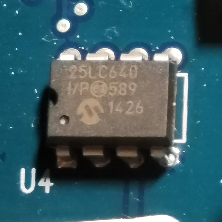
- Alarm System Part 1: The Old Security System: What came with the house when I bought it, and an overview of the chips on the board and a deep dive into how the EEPROM works.
- Alarm System Part 2: System Teardown: Tearing out the EEPROM and socketing it for testing.
- Alarm System Part 3: Dumping the EEPROM
- Alarm System Part 4: The Keypad: What’s making this thing work?
- Alarm System Part 5: How to Hack a Home Security System: Getting in!
First things first, it was time to tear out the EEPROM since the reader is coming soon.
What You’ll Need
- Solder Sucker preferred — a little hand-held device that uses a spring to create a brief suction and pulls the wet solder out of the board. (You may also use SolderWick as well, a woven copper fabric, but it’s just not as cool and is consumable)
- Solder, the good ‘ol death-dealing lead (60/40) stuff works best, but if you’re a plumber or somebody who doesn’t have old stuff laying around (and is rich), silver solder works too. If you don’t have rosin core solder (like, cut it and if it doesn’t look like a tube), you’ll want flux too.
- (optional) An IC socket compatible with the chip you’re replacing
- Some way to pry, I used a small screwdriver — more on this later (chip extractor preferred)
- Soldering iron. Don’t skimp, a decent one is like $60 and you’ll use it all the time.
Finding PIN 1
This part is important — you can’t take a game cartridge and jam it in backwards because that will let out the magic smoke. Same thing applies here.
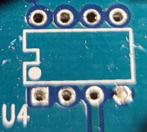
Ensure you are aware where pin 1 is, there’s a few ways to tell:
- The IC (the chip) either has a dot near PIN 1
- The IC has a notch in the black body at the end where PIN 1 exists
- The silkscreen of the board may have either of the above (but you won’t know unless the chip is off)
- The board may have a 1, or a square near PIN 1
- The solder pad on the bottom may be a square in a sea of round pads
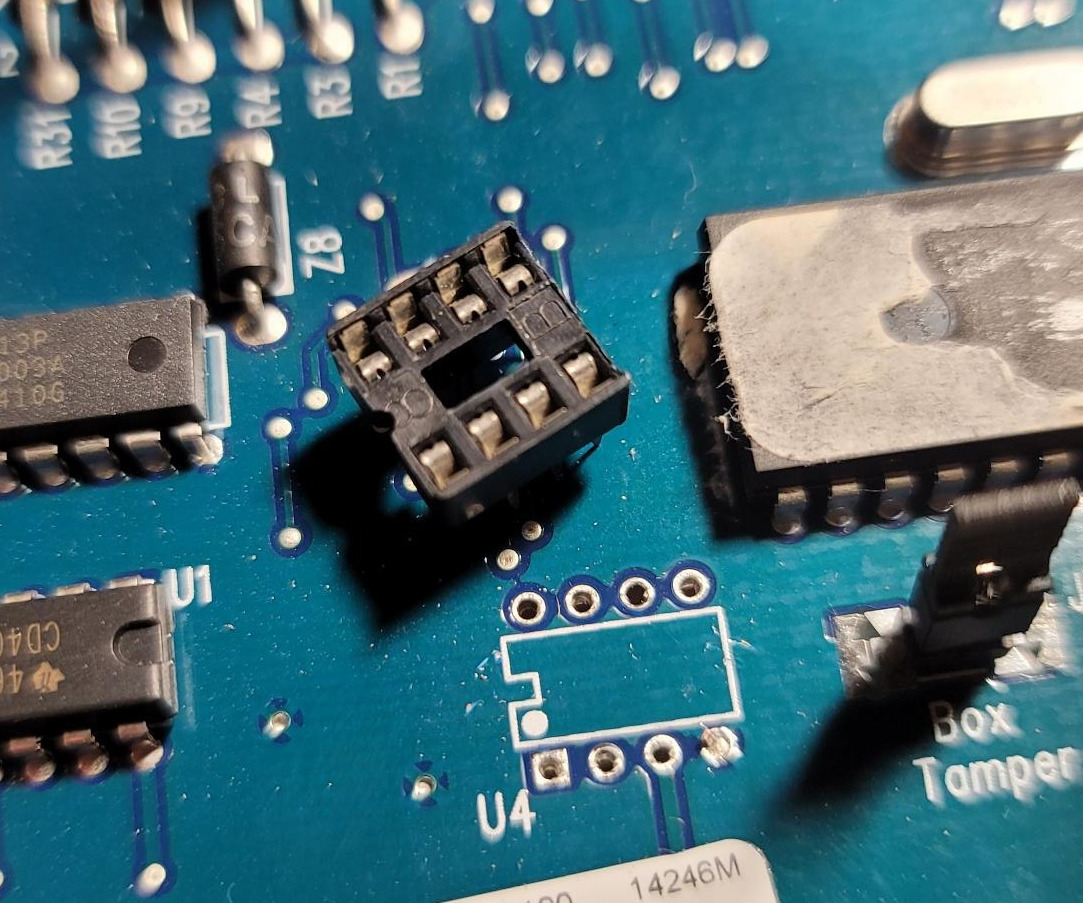
Thankfully, mine pretty much has all of this except the “1” near the pin:
Once you have the PIN1 figured out for BOTH the circuit board, AND the IC, you can proceed to the next step. You’ll need these to ever use this board again. I would suggest you don’t power on the board while in this state, it’s unlikely to matter since this is the persistent memory — but if there’s another system expecting to talk to this EEPROM, it may read data from something that is always “LOW” and replace valid, needed data with all 0’s.
ERRATA: While re-reading the datasheet for the PIC, I noticed that there are actually 256 bytes of non-volatile EEPROM directly on the microcontroller. So, I bolster my statement in the previous paragraph that you should not power this on without being complete.
Extracting the EEPROM (IC, not Code)
Next, heat up your soldering iron, it’s time to pull this bad boy out.
Flip the board over so you can see the contacts on the bottom.
I’d suggest heating up a pin, using the solder sucker to extract the solder from the pin, and then waiting a bit for everything to cool down. Repeat this for all the pins. You don’t want to overheat the IC while you’re extracting it and affect the quality of the data stored or literally break down the chip thermally.
Keep going, you’re almost there.
Alright, you feel good you got all the solder out, you can see nice clear holes with pins in the middle.
GENTLY use a chip extractor, small screwdriver, chisel and hammer or prybar to remove the IC. If you get resistance, probably stop and re-check the holes to ensure there’s no solder.
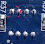
Or don’t and do what I did:
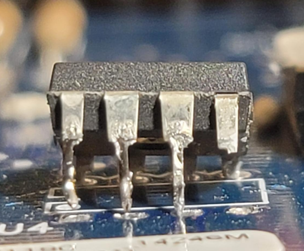
Clearly I was wearing a muscle shirt, drinking a protein shake and feeling a touch aggressive. PIN 4 snapped off in the hole. This is pretty friggin’ annoying but it’s not a massive problem (at least how it broke off), I can just solder on a piece of something there to still read the chip. I may even purchase a replacement one and copy this to that so I don’t have to screw around with trying to get solder-covered pins in an IC socket.
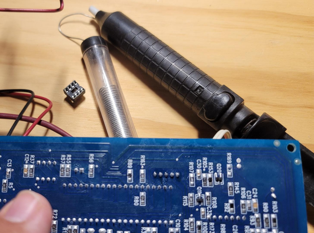
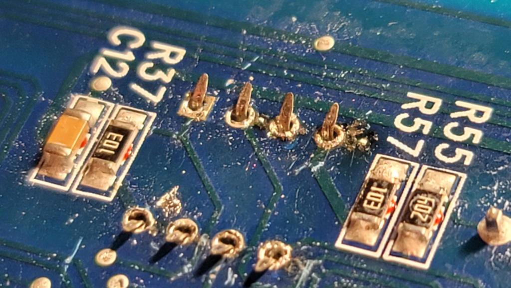
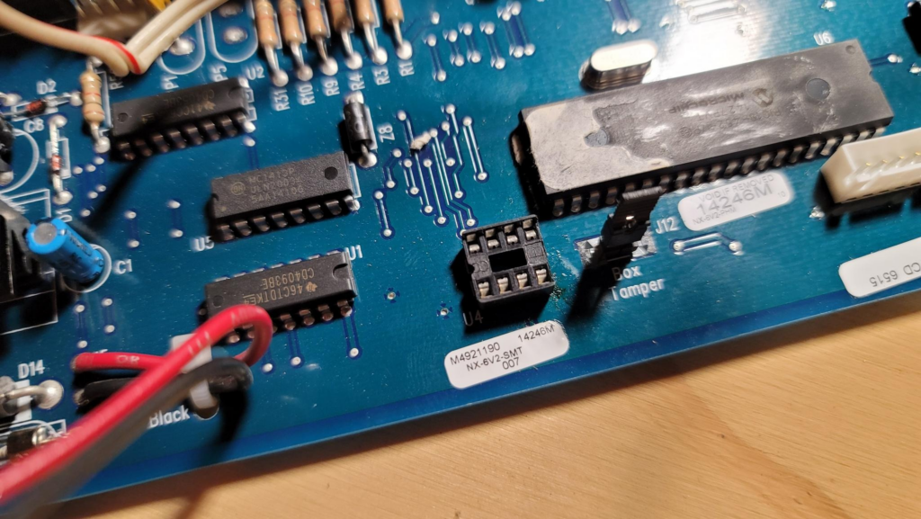
The rest of it came out fine, and then I cleared the broken leg out of the hole and got the socket ready to go in:

(In this photo, the leg was still stuck in the hole for PIN #4)
Installing the Socket
You don’t NEED to install a socket, you can simply read/write the EEPROM with whatever you want to do and solder it back in the board. I don’t trust myself to that extent and know I’m going to keep screwing with this until it’s a total waste. By installing a socket, I can keep pulling out the chip and replacing it without worrying about legs breaking 😀
Next, take the socket and ensure you line up PIN 1 on the socket with the board. Yes, it electrically doesn’t matter where the socket faces, but it’ll make it make more sense when you cram the EEPROM back in later. Same rules apply here, look for a notch or a dot on the socket.
Once you get all the legs through (yes, look and count each one, they are flimsy and fold under the socket), bend the legs over slightly opposed to each other. This will hold the socket in while you solder. This is LESS sensitive to heat than the IC but breaks certainly won’t hurt.
Start with one side of the socket and solder a leg (like PIN 1) — then go to the opposite side and solder the kitty corner (or catty corner / caddy corner if you’re from PA) and solder that pin. This will hold the socket while you finish the rest of them.
Because I hold a Master’s Degree in Electrical Engineering and definitely didn’t just learn how to do this on my own, my soldering looks wonderful and the board is absolutely not scorched at all.
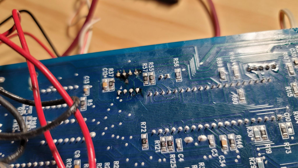
When you’re done, flip the board over and look at the socket. If it’s a melted pile of plastic with pinholes in it, I’m not sure what to tell you.
If not, maybe it’ll look like mine:
In the interim, I’m going to fix the leg on this IC — next time, I’m going to hopefully have the EEPROM reader and we’ll dump what’s in here and see what I can learn. At some point I may make an Arduino read the chip too, but I want a backup in case I’m wrong.
Leave a Reply