
This Blog is part of a Series! Check out the rest if you haven’t already:
- Home Security & I’m Back: A story about how I built my own security system and wrote some software for it.
- Alarm System Part 1: The Old Security System: What came with the house when I bought it, and an overview of the chips on the board and a deep dive into how the EEPROM works.
- Alarm System Part 2: System Teardown: Tearing out the EEPROM and socketing it for testing.
- Alarm System Part 3: Dumping the EEPROM
- Alarm System Part 4: The Keypad: What’s making this thing work?
- Alarm System Part 5: How to Hack a Home Security System: Getting in!
I’ve blogged for years on this domain, and every few years I get sick of WordPress or the server I’m hosting on, delete it, and don’t look back.
This time is no different. By 2026 or so, this post should be gone to the ether, or one of the many archival sites out there.
Today, I’d like to share a bit of a story on how I decided to replace my home security system. Ideally I’m targeting people who have a pre-wired home but nothing beyond a beeper when the door goes off, or people who have been duped into thinking Vivint, a terrible company, was actually a good idea. It wasn’t. Vivint is terrible. I’d encourage you to trigger your alarm bi-weekly and see how often the call center actually responds. I’m not responsible if you do though.
I’m going to share the story of literally deleting my home security and replacing it with something that I built end-to-end, and I’ll share my feelings along the way about how it was from the builder, DR Horton.
If you’re anything like me, or the million of others on cooking sites looking for a recipe and not a damn life story, you can swing over to https://github.com/rlerner/mypanel for that
The Impetus
I’ve been a fan of Ben Eater’s 6502 computer for a few years and I’ve been wanting to build one. In preparation of building my own, I’ve told my wife that Father’s Day this year could include an EEPROM programmer and the 6502 kit from his site. I knew I’d want/need an Arduino anyways so I can probe the logic signals from that and literally anything I’ve kept in a yellow and black tote in my garage for years. so I just hopped on Amazon and bought a knockoff Mega 2650.
I had a BASIC Stamp years ago and wrote some cool stuff with it, and had a servo, PIR, a bunch of LEDs and the like laying around. I found the Arduino silly easy to work with and remembered my brother had given me an Uno back in ~2009. Because I have some weird preservation need, I never used it in fear of blowing the thing up. I wish I used it sooner. I plugged that one in, and configured a piezoelectric element to beep when I’d open and close switches. Easy, simple stuff that you don’t need a microcontroller for, but fun to implement in code and not hardware.
I then got to thinking, the security system on my house is lame at best. I don’t know what the keypad code is from the old owners, it’s not attached to the telephone company (telco) and even if it was, I’m not paying for an analog line where gigabit+ fiber is silly cheap (Texas). Plus, being Texas, you don’t need an alarm system to call the police anyway. You sort of resolve that by yourself.
Bit of History
I’ve worked for ~8 years for a “Security Integrator”. It’s kind of like saying “I’m married to a lawyer” and dispensing legal advice — it’s a bad idea, but because I worked there in a role where I wasn’t hands on, I have a LinkedIn network full of security professionals, and I have to use this Arduino, I figure I’m just as good as any.
These folks on LinkedIn though — they post “panel porn” of perfectly cut wire lengths and beautiful board layouts. I don’t have these planning skills, so if mine ends up looking great (typing this about 2/3 into it) then awesome, but I cobble stuff together.
My System Before
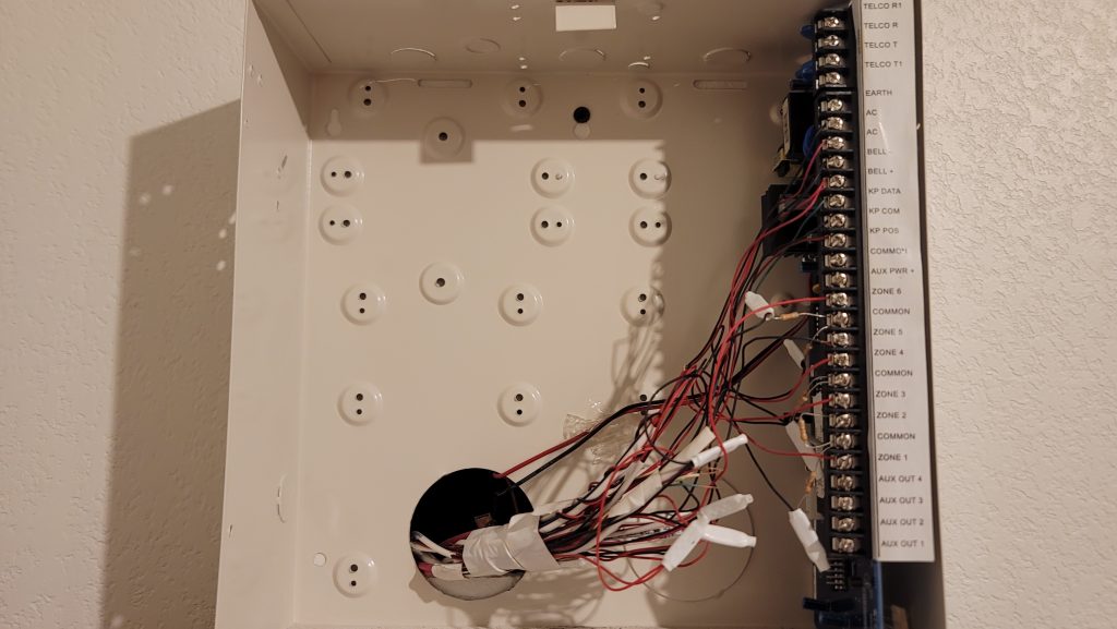
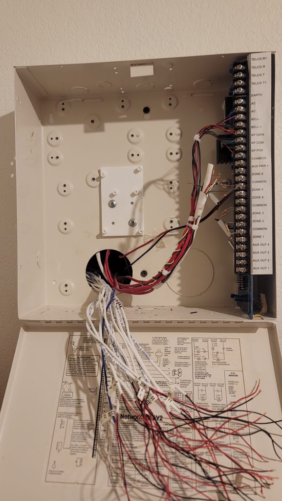
My gut instinct was “it’s not pretty, but it was probably done well”
Here’s what you need to know when you look at a system like this:
- It’s not done well
- The telco ring/tip isn’t hooked up to anything. If I did hit the panic, the cops would never come.
- You really shouldn’t see resistors in the panel. These are called “end-of-line” resistors and should exist (shockingly) at the “end of the line”, meaning at your door, glass break, window, PIR, etc. The entire idea is that we should use a specific resistance that we can apply a voltage divider against, and tell if the line exists in one of three states:
- Open: The zone is insecure
- Proper Resistance: The zone is secure
- Closed/Short: The zone is insecure and compromised
- Obviously, I have a “NC” or normally closed system (meaning the black and red wire should show continuity) and the resistors are there to make the panel happy but actually make the end-of-line resistor concept pointless. My threat model doesn’t include somebody boring into my wall and shorting out a sensor to gain access, and being that it’s a brick house it’ll be especially hard, so I’m pretty fine with this even though I should be angry and ask for a manager.
- The panel I have supports up to 6 zones, however you can easily see that Zone 2 is jumped out with a resistor, meaning my house has only five zones. That sucks because I have 14 external windows and doors to monitor and, if somebody were to open a window within one of these five zones (say it’s Texas, so it’s always nice out) and then somebody breaks in during the night through a door, my dumbass system will smile and do nothing as a result of that change.
- To reiterate, I have 5 zones of detection, 3 of which were independent sensors (I’ll guess they were my three external doors), the other two zones were placed in series. Maybe upstairs and downstairs windows? No idea.
Business Requirements
What do I expect out of my ideal system, based within the above confines?
- I have zero concerns about it reaching out to the police, fire, or EMS.
- I’d like a battery backup. The original system doesn’t have a contingency for that. Thankfully, the UPS that’s backing up my rack already will cover this equipment.
- I’d like as much information as possible when a zone goes insecure (door/window open, etc). So each zone TYPE should have a mildly different chime to it.
- It should be able to call an API or webhook and:
- Notify when a zone goes “insecure”
- Do a periodic heartbeat
- This will allow me to build an at-a-glance view of my home’s physical security posture, in addition to other security mechanisms I have like motion sensors, cameras, and my weird ability to function without sleep and sit outside.
- Also, it will let me know if there has been any interference with the connectivity of my device so I can either investigate my internet issue or investigate who is outside playing with my FIOS.
- Finally, it would be kind of cool to, down the road, build a thermostat using similar hardware, and if a window opens, shut down that AC/Heat zone so I don’t waste money on it.
- It should have a sampling frequency of all sensors of at least 1Hz
- It should detect, at a maximum, all sensors going insecure within one sample cycle. It should only audibly alert once, but the API call should know that all the affected zones are affected.
- It should use Pushover to do a push notification to my wife and my phone
- At this point, I don’t need or want a keypad since a siren will only annoy a robber, and me asking them not to steal is more effective (memesmile.png). So, there is no concept of “arm/disarm”, the system will tell me about everything.
Iteration One
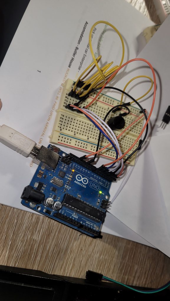
At this point, I think I have 5 zones, so I’m building the microcontroller to handle 6 zones… The 5 in the house, plus one additional to monitor the locked state of the cabinet the security hardware exists in (tamper). Sadly, the tamper switch was never installed by my builder, so I have to figure it out. But for now, yanking a wire out of the breadboard emulates a signal break, so it would trip the alarm.
My kids got a kick out of it.
I eventually realized that there were 14 zones when I had a few drinks, found some wire cutters, and started playing “Spaghetti Splitter” in that panel.
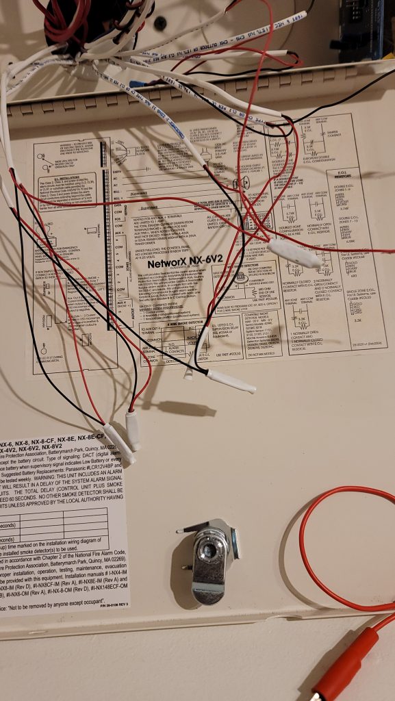
All these white things, which I’m guessing are simply just heat shrink over a crimped/soldered connection, are just daisy-chained zones. These don’t exist any more, I chopped everything off. I also marked each zone with those electrician number stickers, and removed the other items from the system:
- “Bell” which means alarm. I don’t know if that’s legacy nomenclature or just security through obscurity, but I chopped it off because again — I don’t care if there’s a siren. Also I’m too dumb with microcontrollers and amplifier circuits to know what I need to do in order to drive a siren, so I’ll come back to this later.
- KP Data/+/-… This is presumably serial data between the keypad and panel. I plan on setting this up on my desk at some point and finding out for sure, but for now I just took the (-) terminal and will attach it to common. I took the (+) terminal and will add that to my “Chirper” output for the beeper. The green data line I chopped the copper off of for safety purposes and I’m going to ignore that for now. If I ever do make a panel, I’ll use that to serialize data.
Eventually, I realized that the UNO just won’t cut it — it has a maximum of 14 digital pins (I/O), and while that will do a great job of detecting my zones, it rules out both Ethernet and the chirper/beeper circuit. For $20 I can get a Mega 2650 which has an absolute ton of inputs to spare.
Iteration Two
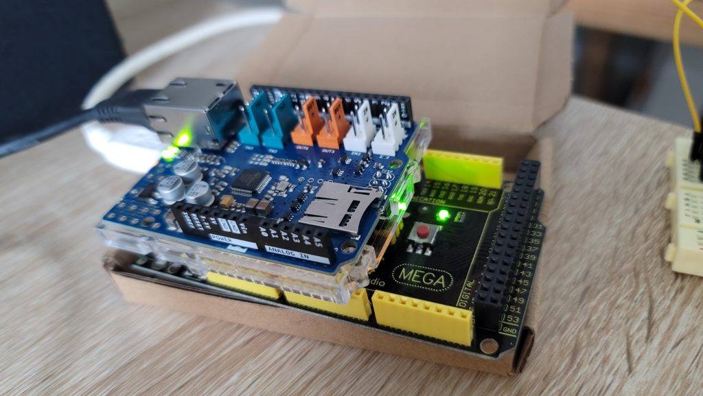
So here we are, thanks to Amazon, a few days later with an Arduino Ethernet Shield v2, which is a cool way of saying “an add-on board that kinda sucks”.
Also, now I’ve moved to the 2650 board with a ton of inputs.
So I’ve updated the code to not used hard-coded zones, and instead use a zone count and iterators to build an array to make this a bit more extensible and take less ROM area on the microcontroller. I’ve then decided I’d use one of my plethora of mildly used domain names as my home security alert system.
If you don’t know me, I work in security. I’ve been interested in security for a really long time, like, as a kid, I got home from school and my parents locked me out. Undeterred, I used a paper clip to pick the screen door and got in. Turns out they were doing a bug bomb or similar. Explains me I guess.
So to that point, all of my domains. Every, single, one, not only uses HTTPS but actively kicks you to it if you request it. I’m not like Google, I don’t care if you have some “weird need” for HTTP. I will redirect you to a site that has a cipher tough enough that you need one of those Rubrix-solving kids just to get in (or so I think).
So I was pretty pissed when I made a request to my server and got back the “You’re trying to speak not SSL to an SSL port” (TLS etc) message. I went back to DuckDuckGo, because my code was as follows:
client.connect("robert-lerner.com",443");Some search result told me I can speak SSL/TLS by using this:
client.connectSSL("robert-lerner.com",443);Which was absolutely bull. After a series of searching, I found out my super new and shiny $35 or so board doesn’t support SSL/TLS. This wouldn’t surprise me because I know implementing it is pretty costly from an implementation view point — especially since the crystal oscillator on my Arduino clocks in at at 1990’s tier 16MHz.
So I had two options:
- Reduce a domain I own to HTTP or buy a new one
- Not do that
I chose “Not do that”. Since I run PiHole (and you should too despite DNS over HTTPS), I already have a “server” locally that can process the GET/POST request and send me a pushover message. I also realize that multicast DNS has inconsistent implementation, so using my LAN hostname may not work. Since my PiHole is already on a static IP in order to actually function as a DNS server, I figured I’d just go that route.
I spent maybe an hour screwing around with the code, but eventually I was able to get back something that wasn’t “Connection Failed” or “400 Bad Request”. Turns out this header actually matters:
Host: 123.456.123.456:80
Which requires the port number as well. I was shocked, I’ve built web apps for close to 20 years. (Damn, dude, you’re old). I’ve assumed HOST was optional for an IP address GET request since it was implied, and an IP factually isn’t a hostname, and would really only be needed for virtual hosting in my mind.
Further, the port I thought was optional since, dude, I’m already talking to you over a port, why do you need me to tell you what port we’re using?
Well: It does.
Once I got past my incorrect theory on port numbers and hosts and got in touch with my inner Bob Lerners-Bee, I got it working.
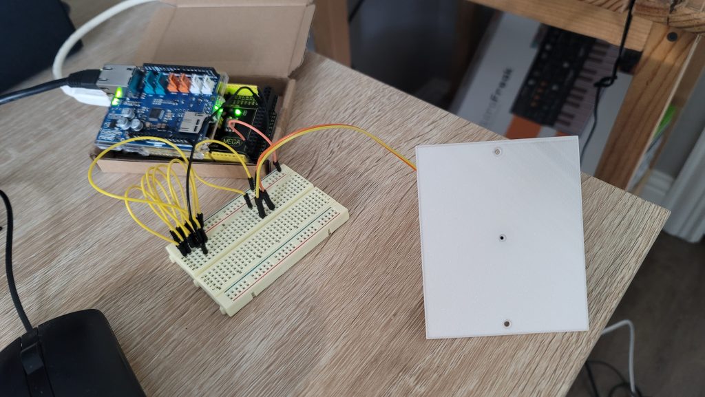
Just like with the UNO, I have this breadboarded out so I can trigger zones manually — I also have a wallplate that I had printed, where the center hole is for the piezo and the outer two are for screws. Annoyingly I did a crap job at my filament purge and there’s some of the black filament in the corner. I may reprint or just paint this, not sure yet.
Additionally, I expected the noise to be a bit louder in the plate since there’s a bit more vibrating mass, however it is about the same to my ears. It does, however, have some weird effect on certain frequencies — perhaps by the interaction of the printed aperture, the “sound chamber” and the piezo, so I adjusted my “ding-dong” alerts to a lower frequency.
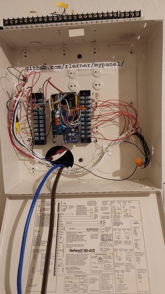
Back at the panel, I’ve cut and marked all of the wire groups to identify the 15 zones, the siren, the AC from the old adapter, and the keypad lines. Most of these had the bare copper cut off and were bent over, tiewrapped, and shoved into the wall. I’ve also attached the 3D printed Arduino Mega wall mount inside the panel, hoping to make room for both of the terminal bars needed.
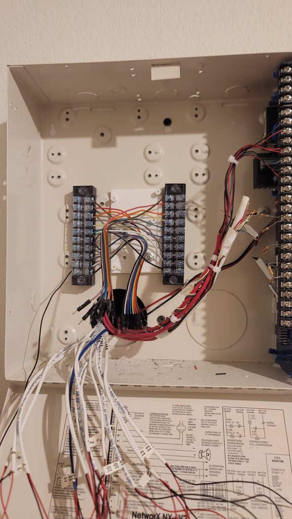
Now the terminal bars are in place. It’s kind of crowded currently.
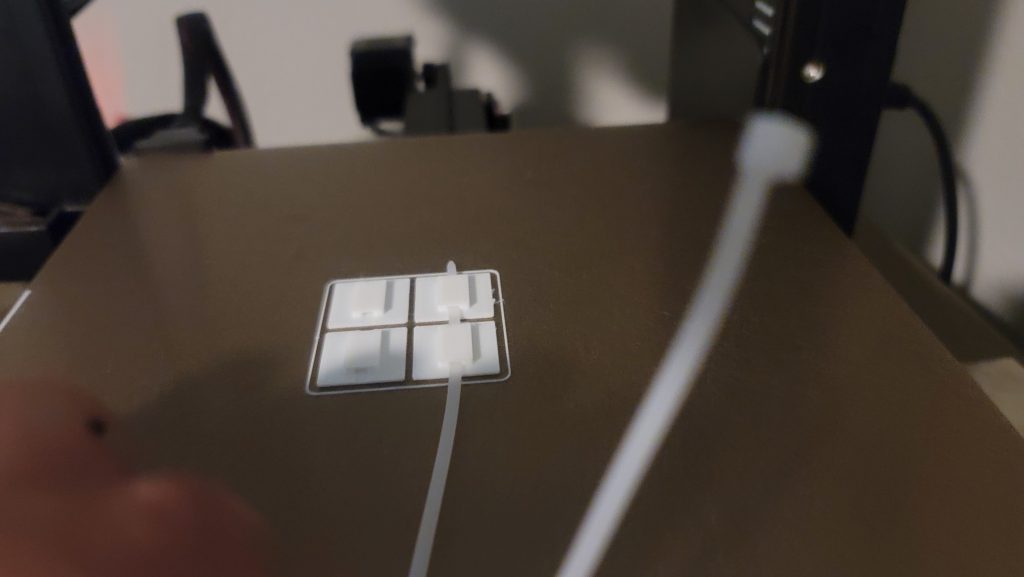
I needed a few cable tie downs and didn’t want to buy them. I 3D printed a few, and used tie wraps and double sided tape I had laying around to tidy up the box as much as I could while I finish development.
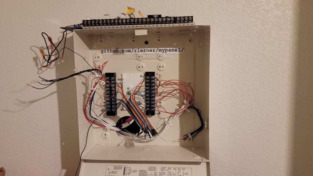
It’s a bit cleaner now — Like a good panel person, I left documentation (but in the form of a GitHub repo). It’s not really “panel porn” and I’m starting to accept this first iteration won’t be.
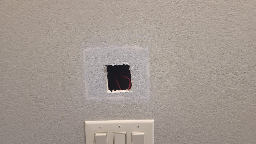
Meanwhile, I took the old panel location and tried to fake the knockdown texture, painted it, and soldered and heat shrunk on some female pins.
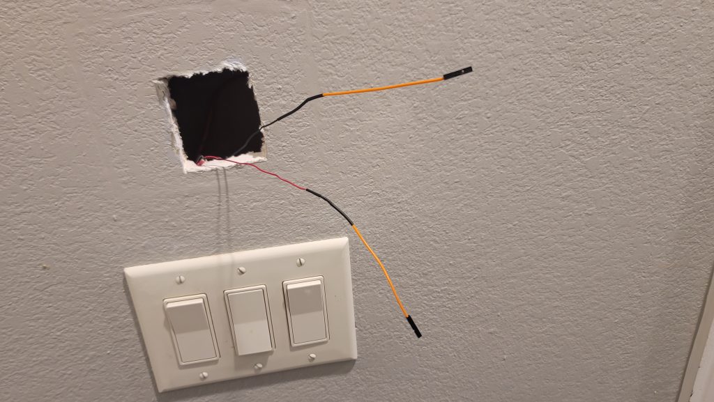
Then added in the chirper panel. I’ll probably come back and add an annunciator here — perhaps a single LED that shows the cycle or state of the panel — or maybe I’ll go crazy and actually use the serial connection here and do something more creative. For now though:
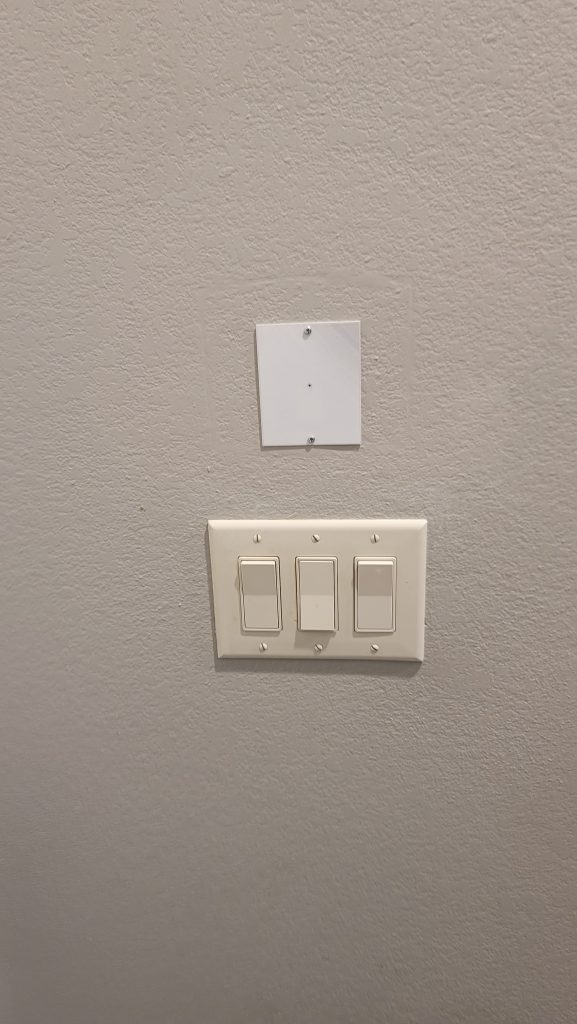
It looks “ok” for now.
Final state of the panel, before ethernet and power.
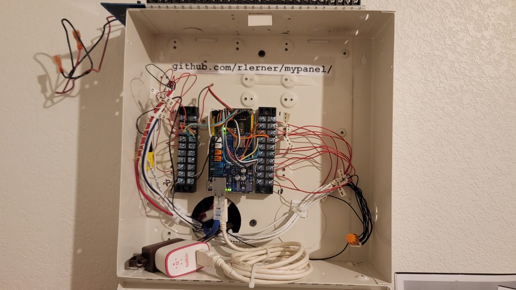
Actively monitoring! Ignore the old panel on top, that’s just there for if I move out!
Step by Step
- At startup, Ethernet and all of the pins will be configured.
- The Zone pins are set as pullups
- Then a current state is gathered of all zones, and a “welcome” or “boot logo” sound is played
- Every 1Hz, a sample of all zones will be taken, compared against their previous state. If it is found that one transitioned into an insecure state, it will sound the chirper and send a web request calling out the zone(s) that have changed state.
- Those entering a secure state are ignored for right now, but I will change this later for live monitoring of door/window state for further integration into a thermostat.
- Every 30 cycles (~30 seconds) the panel sends a web request with a heartbeat. This sends all zone data regardless of state. If this request fails, a small burst beep is played over the chirper and the monitoring continues.
Lessons Learned
- I should have 3d printed some sort of back plane. The standoffs (bumps with screw holes) in the back of the box made some stuff sit uneven or wasn’t as well laid out as I’d have liked.
- Further, I could have pulled the “factory” board right out and made a bit more room for myself.
- I used jumper wires that have pins which fit perfectly into the Arduino, sadly they’re like 22GA stranded, so my strippers wouldn’t strip them and I had to use my teeth. These kept breaking as I put together the panel and I had to fix them a few times. Solid wire would have worked fine.
- I also tried to leave them as a ribbon originally, but the length was uneven as I pulled them apart to the terminal screws, adding tension to the connections.
Leave a Reply