Recently, I had posted about the faceplate of a safe I had found, got to work, and talked about a method of breaching it. I decided to go a bit further and dump the EEPROM, but the contents of it have (so far) meant nothing to me.
I decided it was time to see what was happening in the circuit, but I don’t have an electronics lab because I’m not an electrical engineer. But, I figured I could turn an Ardunio into a simple piece of kit.
The microcontroller involved is Samsung KS57C0502, and the EEPROM I’m specifically spying on is a Serial EEPROM made by Microchip, number 24C02C.
It is an 8-pin DIP, SOIC package with these pins:
- A0 – Addressing Line 0
- A1 – Addressing Line 1
- A2 – Addressing Line 2
- VSS – This is “smart people” for ground (-)
- SDA – Serial Data
- SCL – Serial Clock
- WP – Write Protect
- VCC – Smart people for positive (+)
My plan:
- Grab the Arduino, bond the grounds together between the EEPROM and my Arduino
- Attach a wire to the SCL (clock) and attach that to an interrupt
- Attach remaining wires to interesting pins
- ??
- Profit
I started wiring it up and it came upon me that a few years ago I went to CypherCon in Milwaukee, and a really cool company was there called Sikich. Each year they run the coolest villages I’ve ever seen at a con:
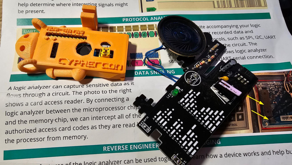
They had simpler circuits you can build yourself like this morse code generator, they also had another one LED strips that you’d solder up, and it was a handheld arcade game. It was surprisingly fun (it’s not pictured here tho, not sure where I put it).
The orange one, however, is a logic analyzer made from a microcontroller that you solder the pin headers on, test it on a live circuit at the table to see UART data flow in within PulseView, and decode a message. It was really fun to play with and unfortunately there’s no documentation I could find online (and it has been a few years), so I didn’t know what pin was ground (though it is kind of labelled in the filament), what channels I could use, what protocol it uses, etc.
They also had a ton of 3d printed shells for them.
But, without the information, I didn’t feel great plugging it in, so I figured I’d dig for another solution and found this:
logic_analyzer by gillham on GitHub
Well that’s easy, I threw it on an UNO I got from my brother many MANY years ago:
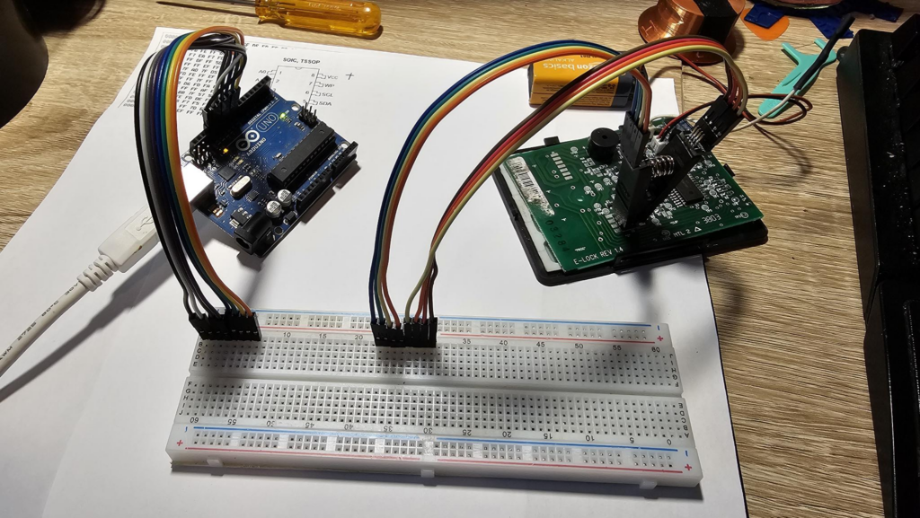
I’m using a breadboard here as a “proxy” so I can make sure I line up the pins correctly, also the UNO has 6 channels, and I have 6 channels I care about.
NOTE: The UNO uses pin #13 for channel #5 (the 6th channel, we count from 0) . It also uses #13 for the on-board LED. The repo warns against using it for sensitive circuits.
Since “sensitive” isn’t specific enough for me to know what that means, so I went against it and jumped to a Mega 2650 instead. This will give me 8 channels, which extra is good, more samples, and get rid of that pin #13 constraint.
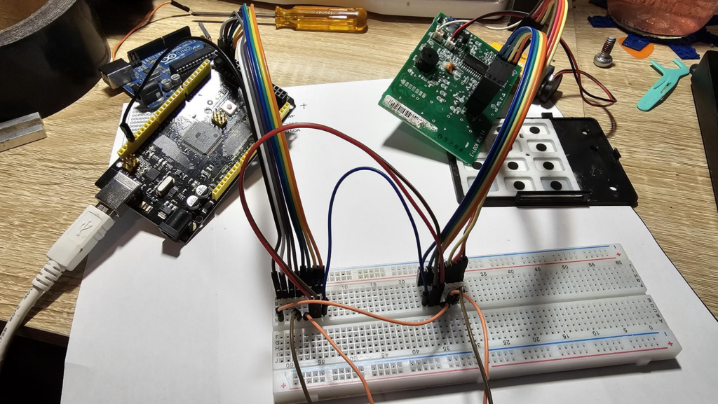
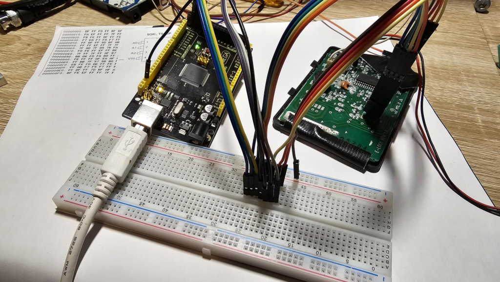
Unfortunately, this is a tremendous pain in the ass. To figure out if I’m reading the right line, here’s the steps to take:
- Find the pin on the EEPROM and look at the corresponding wire color on the clamp
- Follow that to the breadboard and find the corresponding jumper wire
- Follow that to the wire out from the breadboard and map those to
- Follow the outbound wire to the pin on the Arduino
- Look in the actual software above and map the pin number to a channel number
- Go into PulseView and, assuming I remembered that, update the channel number to the chip pin on the EEPROM
This is error prone because people are dumb (me) and will screw that up or not see the proper color, especially considering I used orange and yellow for pins on the IC. Also, this is a cheap breadboard I had from RadioShack probably 21 years ago, with oxidation, etc. So I decided again to simplify:
Breadboard is still a proxy, but I got rid of the + line from the clamp by throwing it in the unused bus bar, I lined up the colors where it made sense, and then I made a conversion table:
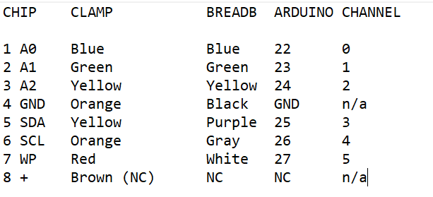
Now I can follow the entire path easier.
How to do it
What you need to have on hand:
- Something to probe
- An Arduino (you can likely use different microcontrollers for this, but arduino has worked best for me for some projects, I had it on hand, and it tolerates 5v well.) You can also use a logic probe that you bought if you want to take the fun out of it
- Jumpers, clamps, probes, solder, wire, etc to attach to the target system
- A computer — I’m using a Windows system because Linux has no games (and this is a gaming rig) but linux will run this stuff just fine, you probably just need to switch around a few things. No idea about Mac, go buy a computer if you want to compute.
Download:
- Pulseview from Sigrok
- sigrok-cli from Sigrok (optional)
- You may need Zadig on Windows, I’m not sure because I had it installed for my SDR projects
- Arduino Studio
- The entire repo I sent above, if you know how to clone a repo, cool, if not, just download the zip and extract it to a folder
Go ahead and install all of these, you won’t need instructions
In Arduino Studio:

Making sure you extracted the entire folder and not just the file (as there are dependencies), open up the highlighted file above (logic_analyzer_sigrok.ino). I didn’t bother with the 2 and 4MHz as I don’t think I’ll need higher frequency readings and figure I’d start with the slower, more stable one first.
It should look similar to this:
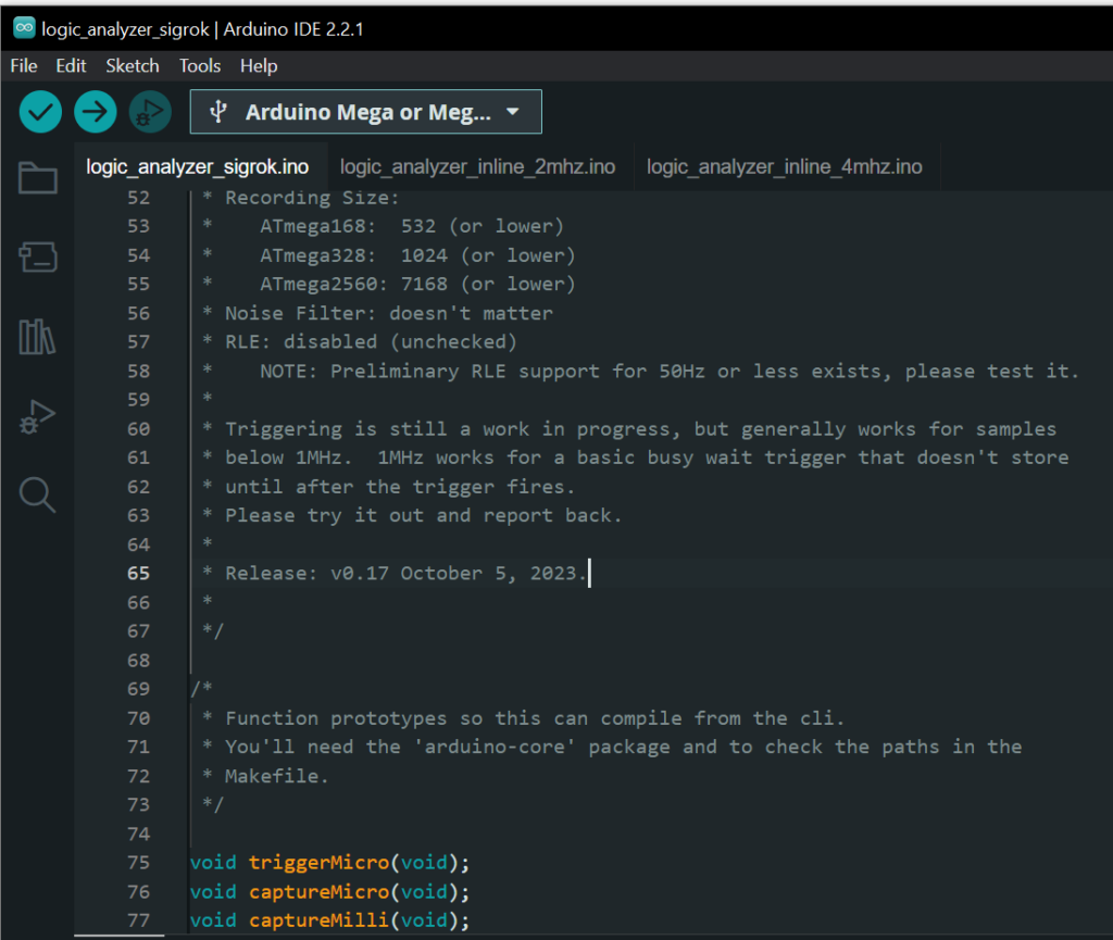
As you can see, I’ve selected my board already (Arduino Mega or Meg….). You will need to do that to compile it and upload it.
SECURITY NOTE: Always review the code you find online for bugs, security issues, and other concerns before executing it. I didn’t do this step because I work in security and arrogantly believe “it will never happen to me”, but you still should.
Ideally, you should upload this before making wiring connections, I’ve had issues in the past with using certain pins on the Arduino. I don’t believe any of the pins we’ll discuss here will matter, but not sure.
The code documents itself
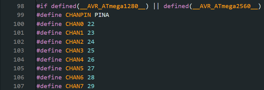
As you can see above, channel 0 attaches to pin 22, channel 1 to pin 23, etc… This is for the 2650 and 1280.
The default pins if you’re using something like an UNO are as follows:
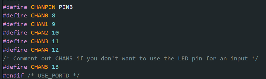
As you can see, PIN 13 is channel 5, and it is called out in the code that it may be an issue.
Wire accordingly — it doesn’t matter what pins you target on your target. Make sure the GND on the target it bonded to the GND on the Arduino, the rest can go to the stuff you are interested in.
In Pulseview…
At the top, select “No Device” and a dialog will pop up:
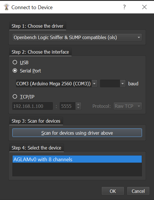
In Step 1, select “Openbench Logic Sniffer & SUMP compatibles (ols)”
In Step 2, select your serial port (yours may vary based on OS, where it’s plugged in, drivers, etc)
In Step 3: Click the Scan Button
In Step 4: Your device should show. If it doesn’t, unplug the arduino, close and restart pulseview, plug in the arduino, wait a few, and start again. If it still doesn’t show up, everybody knows blogs only give half of the information you need and troubleshooting this will take months of reading old Reddit posts.
Once you have the device connected, you’ll get a pretty rainbow with the list of possible digital channels:
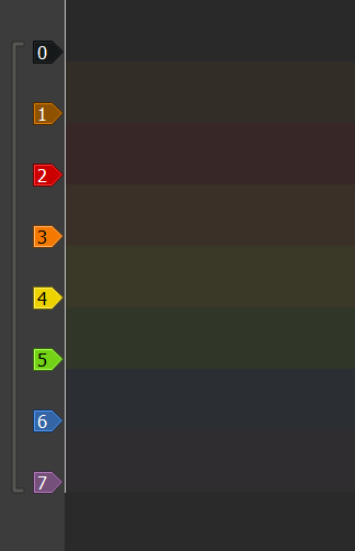
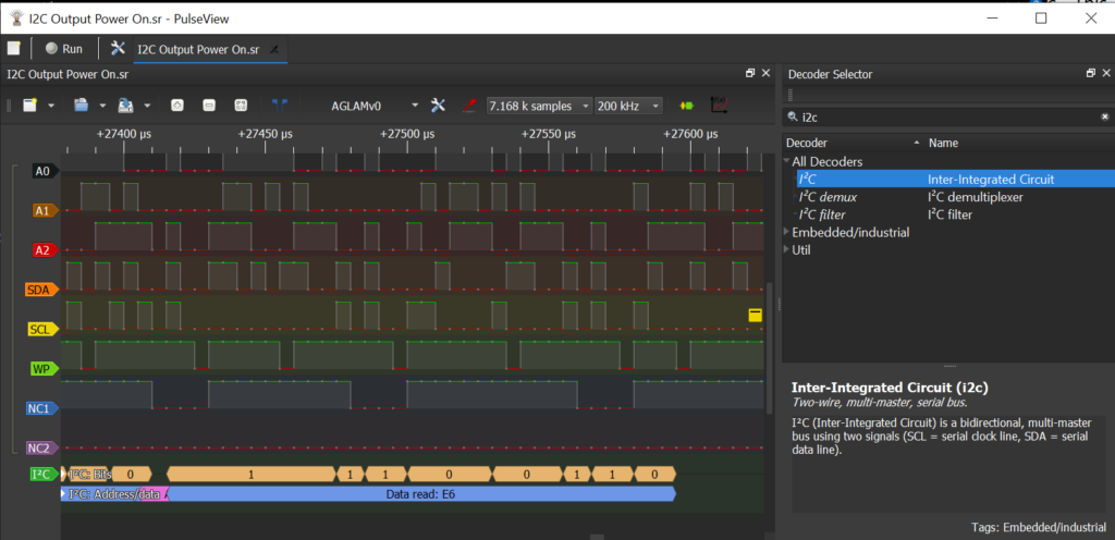
Remember, mine has 8 — so 0-7. We won’t need all of these, but I mapped them out earlier. Double click them and name them what you want, in this case, I used the pin names:

I used NC1 and NC2 to denote they’re “not connected”, but it doesn’t really matter.
Next, click the run button in the top left and make your device send data — could be by turning it on, pressing a button, etc — depends on your target device.
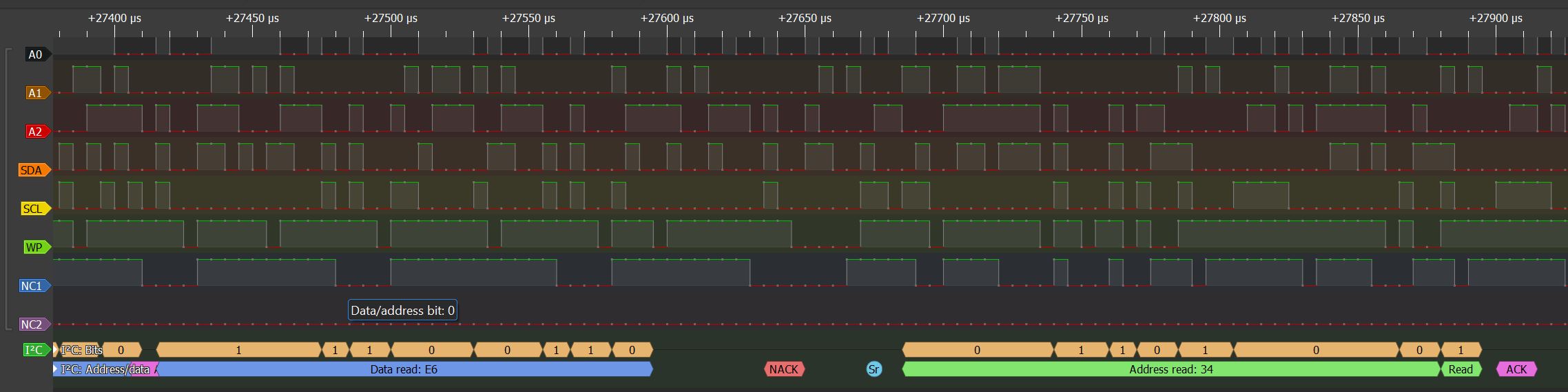
In my case, you can see the data flowing in. I also clicked that green icon at the top tool bar called “protocols” and added an I2C decoder. This read my channel names (SDA and SCL) and knew what to do with it. I started getting some information back. This will work for other things besides I2C as well
Now I have a data dump — and that was the easy part — now I have to figure out exactly what is happening so I can finish my other blog I started about hacking this thing.
Stay tuned!
Leave a Reply