
Atari 2600’s are pretty impressive systems when you consider how many XBox 360’s are RROD’d right now and how many 2600’s are still running. That might be down to simplicity, or maybe engineering!
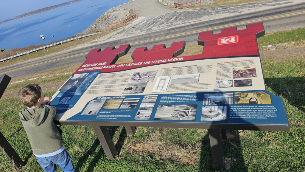
For those of you that don’t know, I’m actively working on building an Atari gamepad with my oldest son. Recently, we took a road trip up to Oklahoma for lunch and to do an Engineering Course, where we seen the Denison Dam and spillway right on the state border:
We also stopped at Carpenter’s Bluff bridge, which is a bit uncomfortable due to the amount of vandalism, trash, and what not in the area, but it’s a cool piece of history showing him a 114 year old bridge with a wagon shelf on the side, juxtaposed to the four lane road crossing the Red River (state border) now:

So it’s late at night and I want to figure out a good way to determine how good the controller is that we’re going to make, but I also realized that I have FIVE original CX-40 Atari Joystick controllers — and only one of them actually works.
Simplicity? Well, according to Wikipedia, it is studied in Industrial Design — though I’m not convinced that’s a good thing.
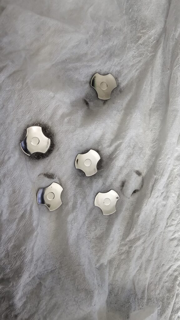
I’m just a random dude, and here’s the failing four I have:
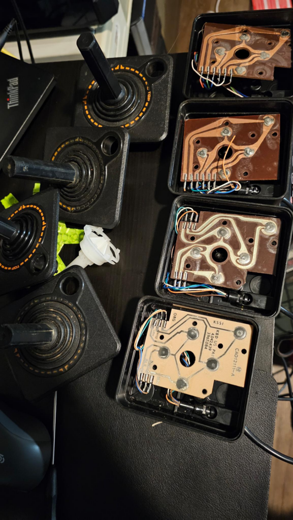
Of those, I clearly have three different designs — different circuit trace routing, different connection points internally. The two I have that are similar also have the top joystick portions with the most intact paint.
The failure modes I’ve noticed:
- A dog ate the top of one of the joysticks — cosmetic and entirely disgusting
- A broken orange wire on the second from the top one
- One had a “Fire button” spring that was out of place
- One had the white part that goes into the joystick and actuates the buttons, broken in three spots
- One has the hump in the middle (see the circle hole in the board) — that supports the joystick completely sheared off.
- At least one, if not several should still electrically work and don’t, which seems to indicate that the connector has failed.
What kind of connector does Atari (and Sega) use?
Believe it or not, it’s a standard DB9 port — or as you may remember it — a COM Port.
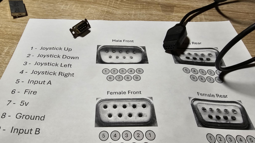
So, I found this doc, which my hilarious asshole friend referred to as “Soldering by Number” and decided I’d build the male portion of it so I can test the buttons.
Thankfully, I bought a new tip for the soldering iron and went to town on it:
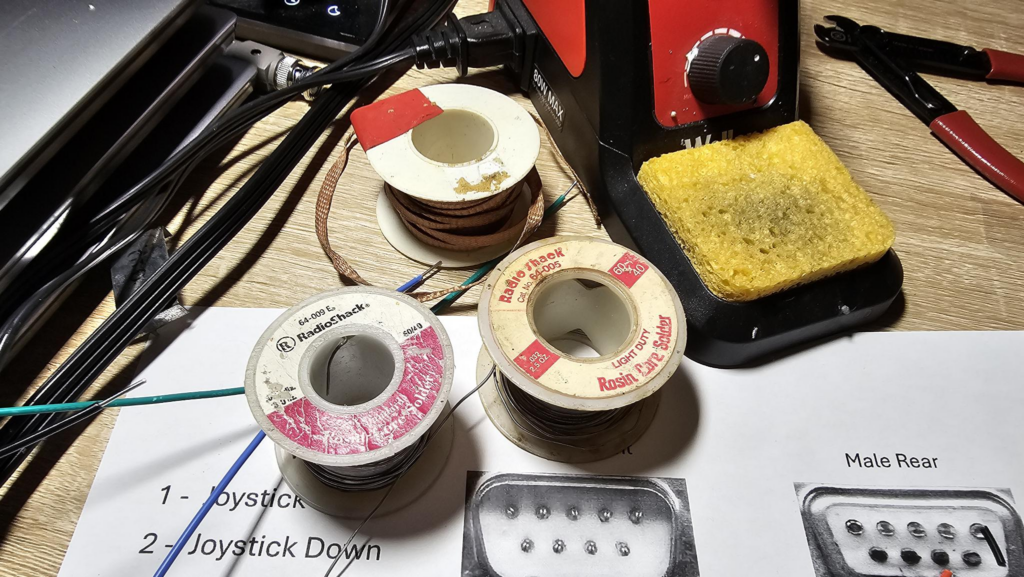
Either I’m old or I don’t solder enough, either way, is 60/40 still used? Or is it all XBox Failing style Silver now?
My Harbor Freight Helping Hands fell apart, but the box for the wire came in handy here:
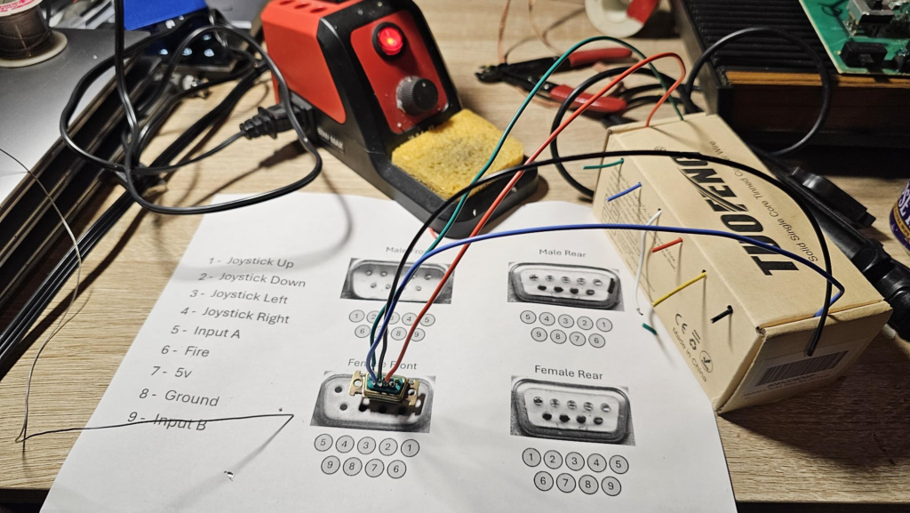
Once I was done wiring it up (there’s 9 wires needed and 5 colors) I did a test with a meter to ensure there was no bridging in my solder joints.
- Pin 1, Joystick Up = White
- Pin 2, Joystick Down = White
- Pin 3, Joystick Left = White
- Pin 4, Joystick Right= White
- Pin 5, Input A = Green
- Pin 6, Fire = Yellow
- Pin 7, +5v = Red
- Pin 8, Ground = Black
- Pin 9, Input B = Blue
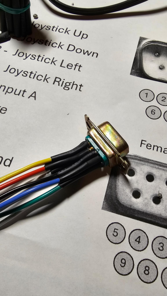
Next, I heat shrink wrapped each joint:
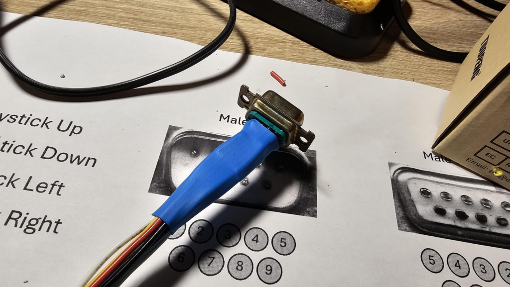
And one more to help stabilize the strain across all of the pins and wires:
NOTE: At this point in this blog, it has been over two months since I added to it. My original plan was to fix these controllers, and use that adapter you see above to hook into an ESP32 and read the controller buttons. Idea was to ensure that there was nothing “closed”, then check each direction (up, down, left, right, fire) and ensure minimal bounce and that other lines weren’t triggered. Frankly, that would be a good way to do it if I were planning on doing a ton of these, but reading a button is a pretty boring thing to do with an ESP32 and I figure that most looking at this are more into learning the how I fixed the controllers. So I’ll be doing that here.
How I fixed the Joysticks Blog by Bobby Drop Tables
Now I’m about eight years younger than the Atari 2600. My childhood was more NES, Gravis Gamepad, Sonic the Hedgehog. So when I tell you that the 2600 joystick is shit, it really is shit and you only like it because nostalgia tells you to. Yes, blah blah marvel of engineering, pioneer this and that. I don’t care, it’s 2025 and using this controller still is awful. That’s why I made a gamepad for it that I just realized I never published a second part of.
That said, people love these and they want the “genuine article” as John Candy says. So lets do the right thing and keep these out of the landfill.
Across ~10 of them, these are the common failure points I’ve observed:
- The DB9 connector is split by design, this allows it to flex and provide tension against the pins of the other connector. Problem is, these become bellended over time through torsion from people pulling on them, repeated insertions and the like. Eventually, they stop making contact and there’s no easy replacement other than replacing the wire itself.
- The original units use Molex-style connectors to attach to the board, while these are not bad by themselves, when you replace the wire they will likely break — and the new wires usually don’t come with the connectors, and the portion that is attached to the wire is crimped. This means, once you take them off, it’s about it. Even if you do reconnect it, it lost some strength and may cause intermittent connections.
- The joystick assembly internally that connects the actual action to the buttons is made in such a way that it is easy to break, especially over time with aging polymers.
- Nearly every joystick I’ve encountered has some sort of teething damage on it. This is especially weird since I’ve never had animals that chewed on things and the Atari out at the same time. That said, I had some family members who may have.
- The silver dome switches provide a really nice tactile sensation but the exposed copper traces can oxidize and corrode, providing inaccurate signals
- The joystick action pivots on a center piece. This can (and in my case on one) has snapped off.
- The paint wears off on the ring around the joystick due to friction from hands. Do note that the Darth Vader style consoles ship the joysticks intentionally fully blacked out and I’d recommend keeping them original
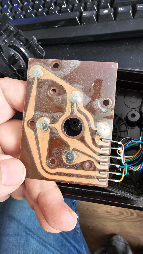
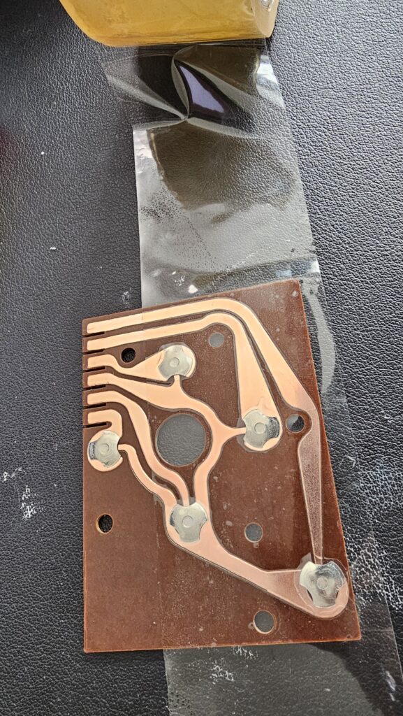
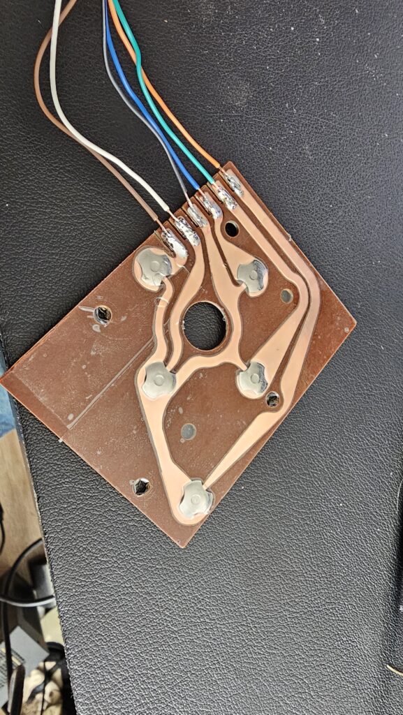
Here, you can see the silver dome switches that seem to be protected by packing tape and apparent dirt or moisture under them. You can also see the molex connectors on the board.
So, how do we address this? Easy:
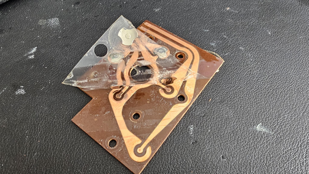
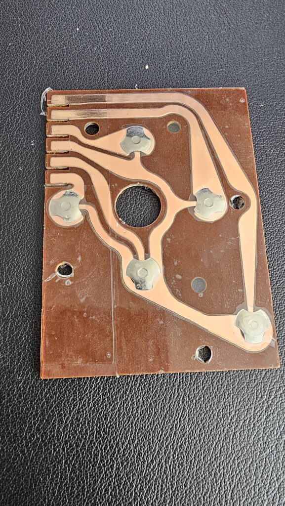
I peeled this shit off. Keep the metal domes, keep the circuit board, and throw the tape in the garbage.
How to clean the circuit board
You can probably use Goo-Gone or Goof-Off or similar, but I used what I had on my desk – WD-40 and paper towels. This removed a great deal of the adhesive. For what remained, Isoproyl alcohol and a paper towel worked really well. After this, I took the board in the sink, washed it with dish soap and water to remove skin oils, WD-40 and any residue off.
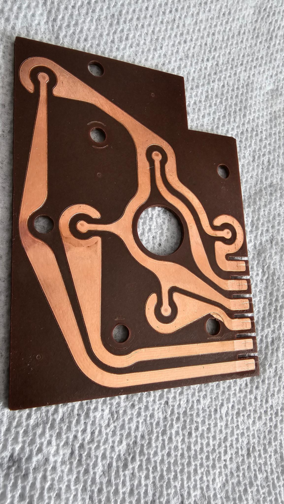
It’s better, but it isn’t perfect yet. You can still see some discoloration, which points to oxidation.
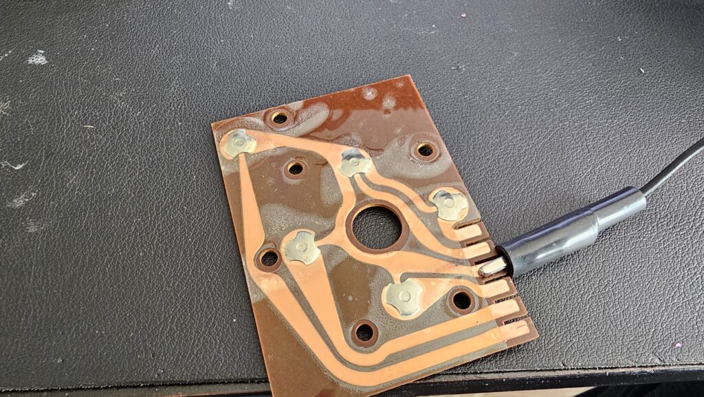
So, the next step was more paper towel, but in this case I also used Mother’s Mag Polish. This stuff is made for car rims, but is incredible on some metals like aluminum and copper. If it turns black, that’s oxidation coming off.
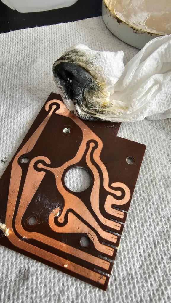
Looks worse, but it’s better. Once I went over all of the traces by rubbing hard on them and then following up with a clean piece of towel, I then washed it up in the sink again and then hit it with a cotton ball with more alcohol to remove any remaining oils and contaminants.
Next, do the same with the domes:
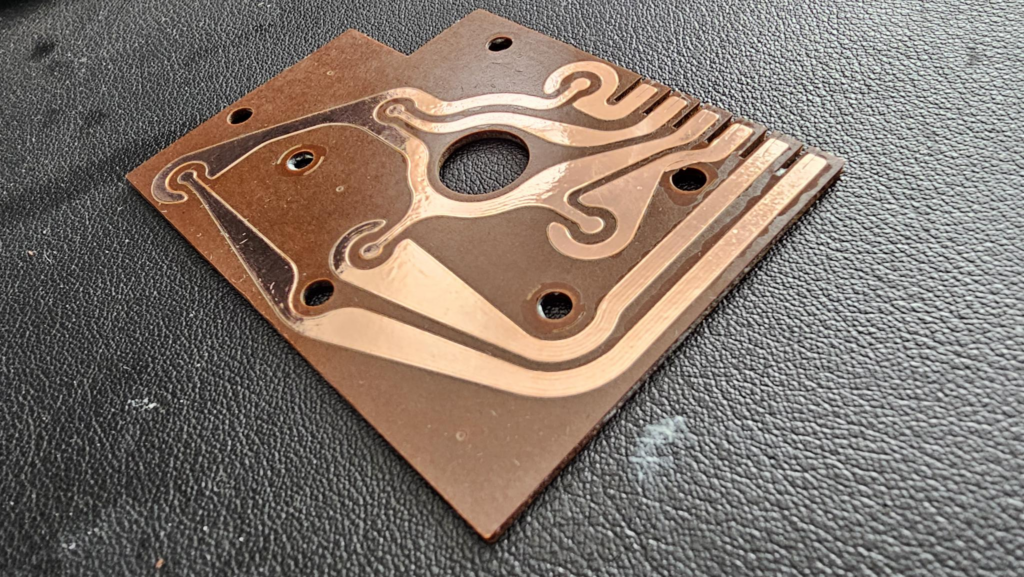
Using enterprise-approved aerospace grade packing tape, reattach the dome switches:
Pay close attention to them, there are three areas they contact the board and none of them should touch the trace that leaves the board. Make sure you don’t tape over the area shown in the top left above, you’ll need to solder there later.
Here is the completed board — you can use an eraser or your finger to push out most of the bubbles, and an Xacto or razor knife to trim it. The holes in the board will also need to be cut out for screws and the pivot for the joystick action.
Above, is an obviously out of order picture of me allegedly testing each of the switches before I assembled it. While I did do that, I didn’t take pictures I guess.
Using the harness I showed earlier, make sure you map the replacement cable correctly, slip it through the base and then solder it to the board:
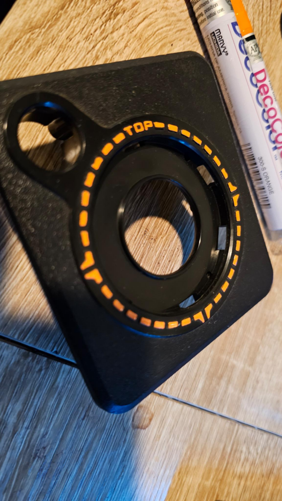
Now, reassemble. I have not bothered designing a new rubber part of the joystick and instead took the “Best I had” and moved them to the joysticks with the best paint, in fact, I even designed a replacement bezel that unfortunately needs to be glued in to work:
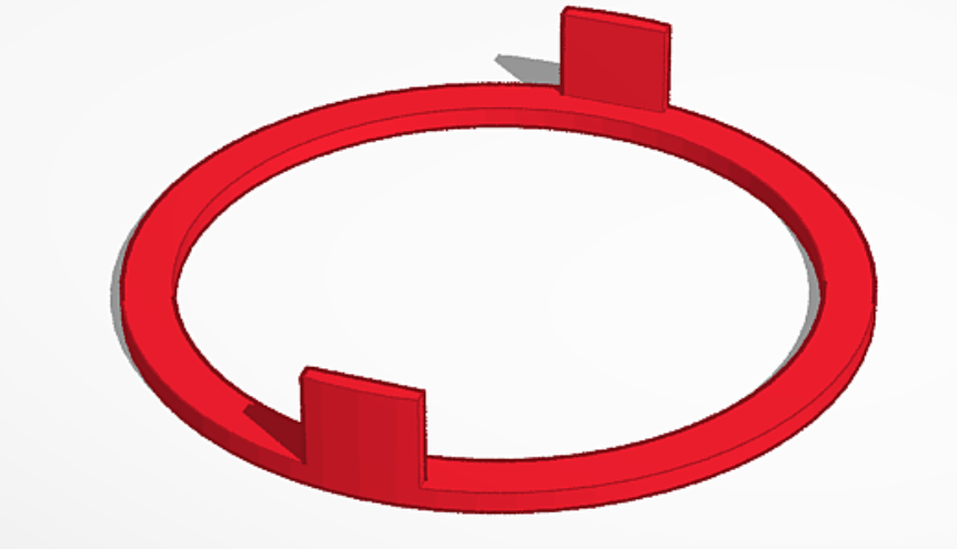
That said, once you print it and put it in with black PLA, as long as you have a PEI bed it’s unlikely to be noticed:
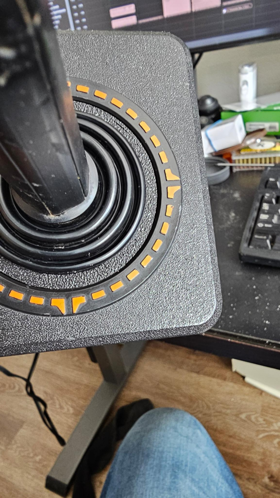
Last part, I bought “Deco Color Orange” paint markers from Hobby Lobby — they have them on Amazon but they’re a lot more there. I then painted the worn joysticks:
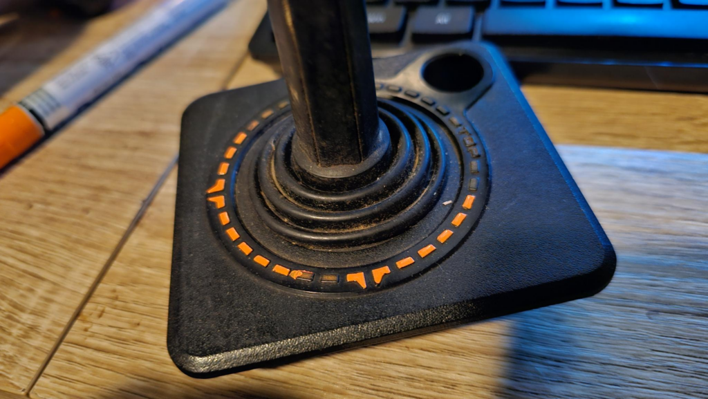
You’ll see here I made a few errors, but with some rubbing alcohol, it cleans right up. I’d recommend picking up both a fine and a broad tip. The word “TOP” at the top of the controller is really difficult to get done nicely with the broad tip.
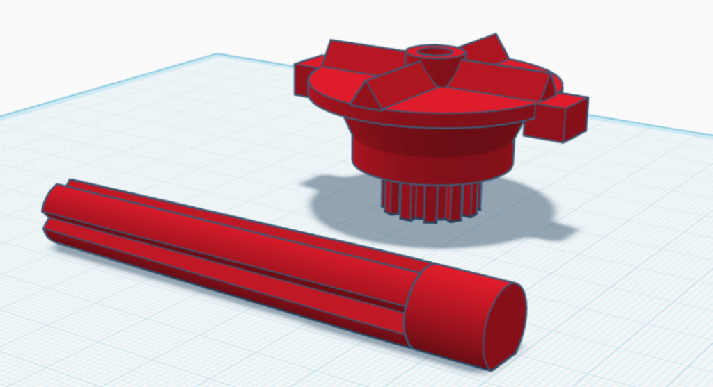
Lastly, for the controllers with a broken joystick action, I designed and printed these. The idea being that the layer lines provide strength, and the “+” shape of the controller stick should add more wall adhesion. Other improvements to it will prevent it from breaking in the future by adding a more robust design to the switch bumps…. I only have these if I absolutely need them:
Put it all together and go tear up some Pac Man, or ET, or Grand Theft Auto 2600.
Leave a Reply