Quite some time ago, I built a Ben Eater 6502 computer. It was fun but frankly I’m too nervous to do anything cool with it but follow his tutorials.
I wanted to take the clock circuit and order a PCB and 3d print a case that allowed me to switch from stepping, astable, bistable, and crystal-sourced clocks — but to do that would mean I have to source parts and I really hate doing that.
I got the idea that I could build a clock circuit with an Arduino. Should be easy, but alas, let’s do napkin math:
If I use “digitalWrite()” High, followed by a delay(), then a Low, followed by a delay(), assuming I set those to 1ms each — that means that I’m at a 50% duty cycle (which is what I think you’d want for a clean clock signal, but somebody donate an oscilloscope to me so I can figure that out). That means that each “rising edge” of the clock signal would be ~2ms apart.
2ms would happen 500 times in one second (500 * 0.002), which means that my clock circuit would peak at ~500Hz. That’s cool and all, but it isn’t exactly all that fast either.
So I did what I do, and I asked AI to generate some code for me, and this is what I got back:
void setup() {
  pinMode(8, OUTPUT);  // Set pin 8 as output
}

void loop() {
  PORTB |= (1 << PB0);  // Set pin 8 HIGH (PB0 is pin 8 on most Arduinos)
  delayMicroseconds(1);  // Short delay
  PORTB &= ~(1 << PB0);  // Set pin 8 LOW
  delayMicroseconds(1);  // Short delay
}
A microsecond is 1 millionth of a second! That’s impressive, which means in this case, if I have both delayMicroseconds() set to “1”, then that means it’ll take 2µs per cycle and I should peak at ~500kHz. But, the code takes time to execute and so do transistors and the like.
For the test here, I’m using an “Arduino Uno”, but it’s a bit older. The chip is an Atmel ATMEGA 328P-PU (P,U… means it stinks? Not sure). Apparently this can peak at 20MHz, which won’t equate to the switching speed. Additionally, my eyes are telling me that it is running on a 16MHz crystal, so I obviously have distrust on that.
So I decided, I have an HP 5315A Universal Counter from friggin’ 1979. That’s right, the year after the best movie ever was released (Smokey and the Bandit, not that nerd shit Star Wars).
Let’s do some testing?
For the test, I stepped through several different delays — remember, they’re doubled — we delay before we turn it on, and then again before we turn it off. GOTO 10.
The table here shows the setting (in microseconds per delay), the calculated (predicted) Hz, and the actual we got out from the microcontroller. Arduino Docs specifically call out that delays over 16,383 using the delayMicroseconds() become unstable, and holy crap is that true. For example, I set the delay to 1,000,000 as a test — we should have seen 0.5Hz as a result. Instead, we got 865Hz. As the docs call out, switch to using delay() for anything slower than that value.
I was quite happy to see how close the numbers were for most of this, the doubling was predictable-ish, but once we got above ~25µs you can really start to see the actual Hz drifting. By 10%, then 24%, and then more from there. So, this table serves to give you an idea of what you can expect — but maybe you can’t, as I suspect the shorter the µs value, the more this depends on chip temperature, ringing and reflections in the probes, and for all I know, cosmic rays slapping my wires.

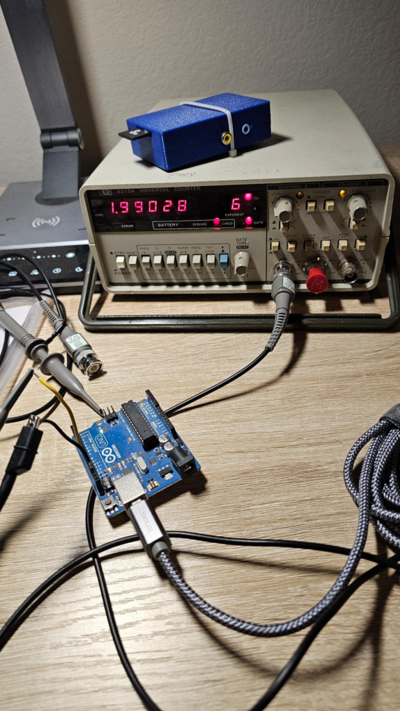
Yes, that’s correct. 1µs is somehow operating just under 1MHz — despite the technical maximum being 500kHz, and expecting lower. Here’s the pic:

Here the deviation is on a linear chart, which is really good for selling how messed up it gets at faster speeds:

That same data on a Logarithmic scale:

So, overall, it’s not too bad within the predicted range of the frequencies
I should mention that the probes I’m using are rated for 100MHz, and this counter is as well. It does use it’s own timing source and I’m not feeding an external, potentially more reliable timing source — so it may have drifted in the 45 years since it was built. I’m not that old, thankfully, but the antique store had it for $6 and I couldn’t pass it up.
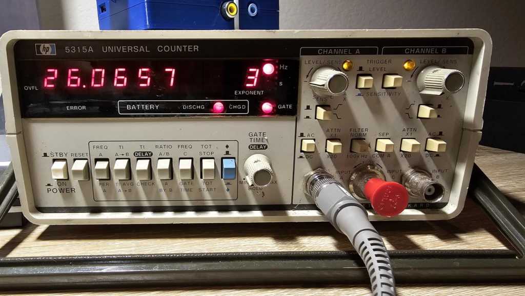
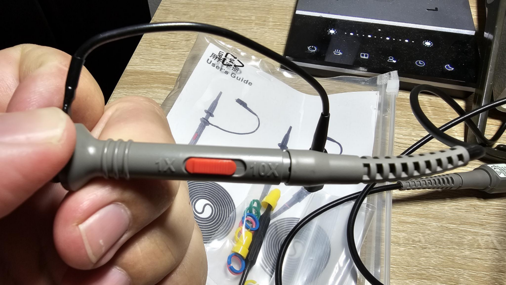
If you want to duplicate this test, here’s the panel of settings as well as the probe that was set to 1X:


Who am I kidding? Nobody is going to try this! This is for my memory when I can’t figure out how to dial this in next time!
Last minute edit! I speak in charts now, here you go!


Again, a 1% drift is whatever really, for a breadboard computer. But damn, that spiked like other unreliable measurements of things that I won’t mention here!

Leave a Reply