Several years ago, I had added accessory lighting to my tractor since I used it to pull a trailer of stuff around my property and to plow a 200′ long driveway after work. Since after work is usually after 5pm, and during winter it’s dark, I wanted to be seen by all of the meth heads in my old area.
Bought a Alpena Amber Twin Strobe Light from AutoZone for like $30 (They’re $43 now…wow). I wouldn’t recommend it. All of the LED products I’ve bought from AutoZone seem to fail prematurely.
I eventually tore the failing LEDs off the tractor when I moved to Texas where snow doesn’t happen, but never bothered to remove the controller unit (turns them on, off, controls flash patterns, etc). I also thought I had disconnected the connection to the battery terminals.
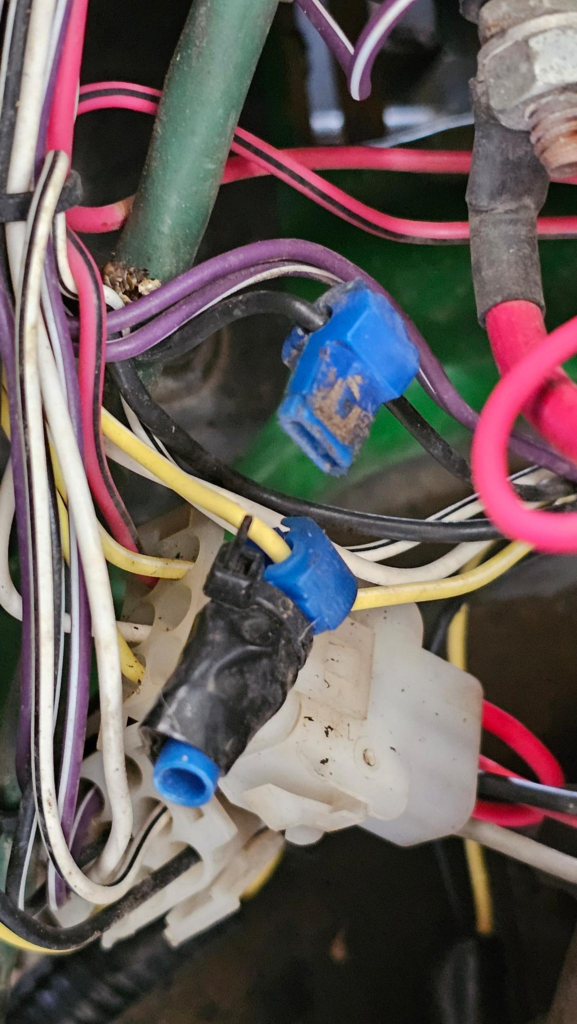
Guess not — looks like I T-Tapped into the 12vDC, fused, switched side. I guess it’s nice that I thought ahead about tying it to the ignition, but somehow that created a parasitic draw on the battery and, being down here, I only need my tractor occasionally (no property, no snow, grass only grows the two months between drought and chili). So the battery does not have the opportunity to be recharged by frequent usage.
I’d caution my readers that T-Taps are wildly convenient: I didn’t have to strip, cut, solder, heat shrink, or anything else. I just put the T-Tap on the wire, close it, it cuts the insulation and provides a spade terminal that I can tap into. They also somehow are magnets for corrosion and it is a guaranteed failure point in the future when the copper dissolves within the wire.
Parasitic Draw?
So after disconnecting some of my other “creative wiring” from the tractor, including defeating the reverse lawyer switch (it actually kills the PTO if you go in reverse unless you hold a button down). I decided I’d look into my now defunct LED controller:
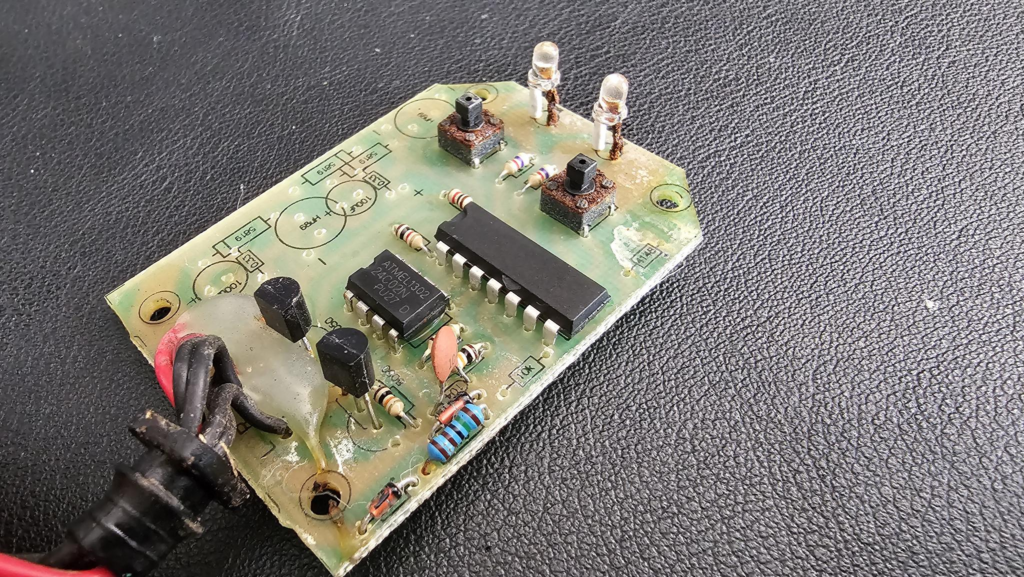
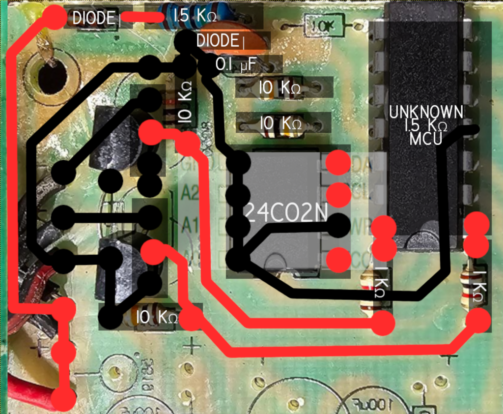
Pictured here without the cover, you can see the absolute pile of corrosion on the momentary switches and on one of the legs of the LEDs. You can also see it has a 14-pin DIP chip that is unmarked, and checks notes… an EEPROM (yay, my fav). The EEPROM is an ATMEL 24C02N.
I’m a bit of a fan of bigclivedotcom on YouTube, his style is to scan in the boards, print them out on big paper, flip the components, and explain them. I don’t have a color printer, this isn’t a video, and I have really sick GIMP skills.
I’m lucky because this is a single sided, single layer board. What this means is that every single trace on the board is on the bottom, so I don’t have to worry about “vias” (connections between layers of a circuit board sandwich) or traces I can’t see. The only small exception is that there’s a jumper where the power comes in under the hot glue.
So I begin:
(Note that the microcontroller says 1.5KOhm, copy/paste error, ignore that)
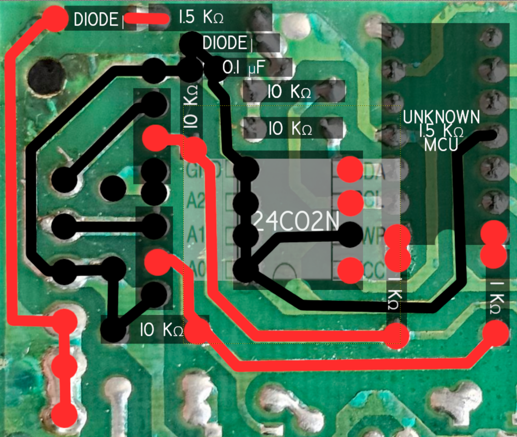
I have a ton of layers going:
- Board Bottom
- Board Top Flipped (lines the components up)
- Polarized Pads
- Traces
- Component shadows (the dark boxes)
- Several component names (the white text)
- As well as that IC pinout for the EEPROM to use as a way to visualize where things are going.
Let’s look at the same view, but with the topside components visible
This is still a work in progress, I have no plan of mapping out the missing components, I still have to map in all the traces and transistors at this point.
FUN FACT! Mechanical keyboards are terrible! Thattt’s right! I have a Razer keyboard that is only a few years old and has terrible debouncing orrr contactt cleaning measures. See these typos? Every few keystrokes shit just “reeeeeeeeeeeepeatttts!” Instead, get a membrane dome keyboard and just slam the keys hard, so you can still be annoying AND type accurately!
Few things I’ve noticed:
- The input for this is for sure 12vDC (give or take, a charged car battery is 13.8vDC, a low one is much less).
- The EEPROM lists:
- 2.7 (V CC = 2.7V to 5.5V)
- – 1.8 (V CC = 1.8V to 5.5V
- There is no voltage regulator or transformer in this setup
- Must be a voltage divider with all these resistors! More on that later.
- The pins on the EEPROM are bonded to GND:
- GND
- A2
- A1
- A0
- WP
- The only reason I can think is that you can’t leave the address lines (A0-A2) floating so they’re tied low, and WP pin low enables write protect? Let’s look!
Datasheet Time!
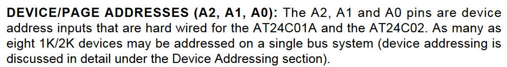
It appears the address A0-A2 pins are simply used to address different EEPROMs on a system, there is only one here so it is unnecessary to find others.
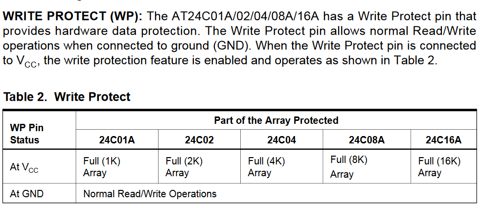
Here, the WP pin (Write Protect) seems to protect the data when it is (+) and enable reading and writing when GND (-). I’m a little surprised by this, I figured the EEPROM would only contain flash patterns and that would only require reading the data. Of course, this could have been made this way to allow manufacturing equipment to hook up and set the EEPROM data while in the board too. Hard to tell.
If you’re curious, the datasheet for the two transistors is located here: SS8050.
Final Board Images
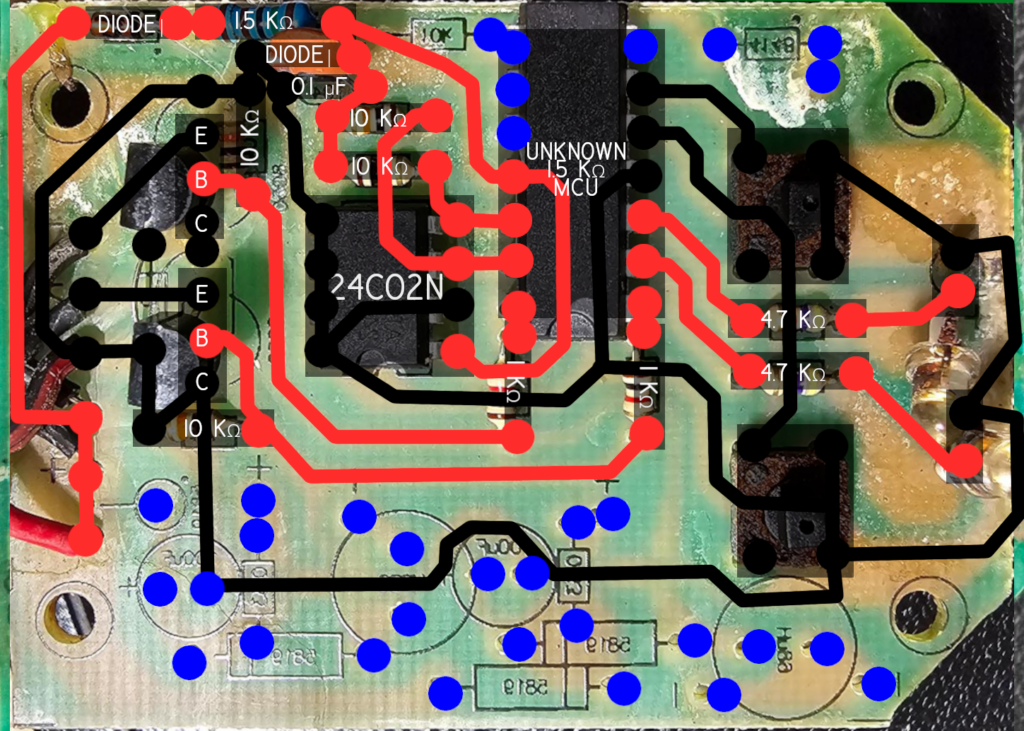
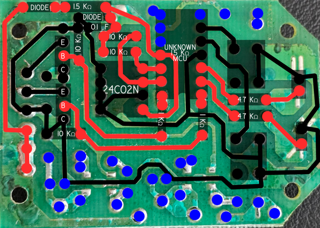
I made any pads that were not connected to anything else “blue”, this was a way to ensure I did a visual check of them to make sure I didn’t miss anything.
I’ve had really bad luck in the past just taking a multimeter to a board something something too many volts, so I think what I’m going to do is pull the components I care about, socket them, and leave the rest.
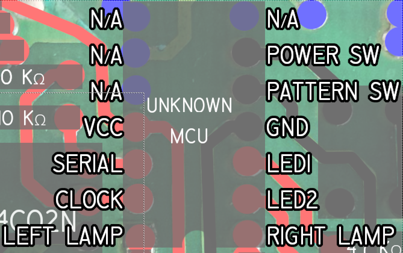
I’ll make a few assumptions about what the pins on this thing might be:

Again, I’m not an EE. Maybe it shows! The NC ones aren’t connected to anything (not connected = NC). That doesn’t mean anything since these pins may be useful, may use specific polarities, etc, and they might just not have been needed for this application. Also, damn, the 1.5KOhm is still there. I need to fix that.
Maybe we should also kick out what the pins appear to be doing functionally:

NOTE: This could have all been done in one of those crappy Chinese epoxy blobs, but for some reason they chose disparate, through-hole components, and I sincerely thank them for that.
Now there are a few different approaches:
- Look for all 14-pin DIP MCUs that operate at ~5v, with a functional pinout, socket the chip, see if we can dump anything from it and/or write anything to it, and validate that the instruction set makes sense
- Realize that I bought a certification audio book and can stand to lose some weight, and go for a walk and come back to this in a few days.
I’m going with the second one, see you in part two!
PS: I’ve added an EEPROM category on my site since that’s apparently my new thing. Going to add old blog posts to it as well.
Leave a Reply