If you aren’t comfortable around electricity, don’t attempt this. Consult a professional. Make sure nothing is plugged in. Doing this may impact the warranty of the device or prevent the resale of the device.
It feels like the plethora of garbage you can buy on Amazon is just designed to sell more USB power bricks and chew through Amazon Basic’s batteries. Christmas is around the corner, and as most parents know — so is firing up a P1 Phillips Screwdriver and a Battery Daddy.
I don’t like creating waste, not because of the environment, but because I have to pay for the waste. That’s why today we’ll be modifying a Minecraft Creeper alarm clock — a game where it is not only acceptable, but required, to walk around punching trees.
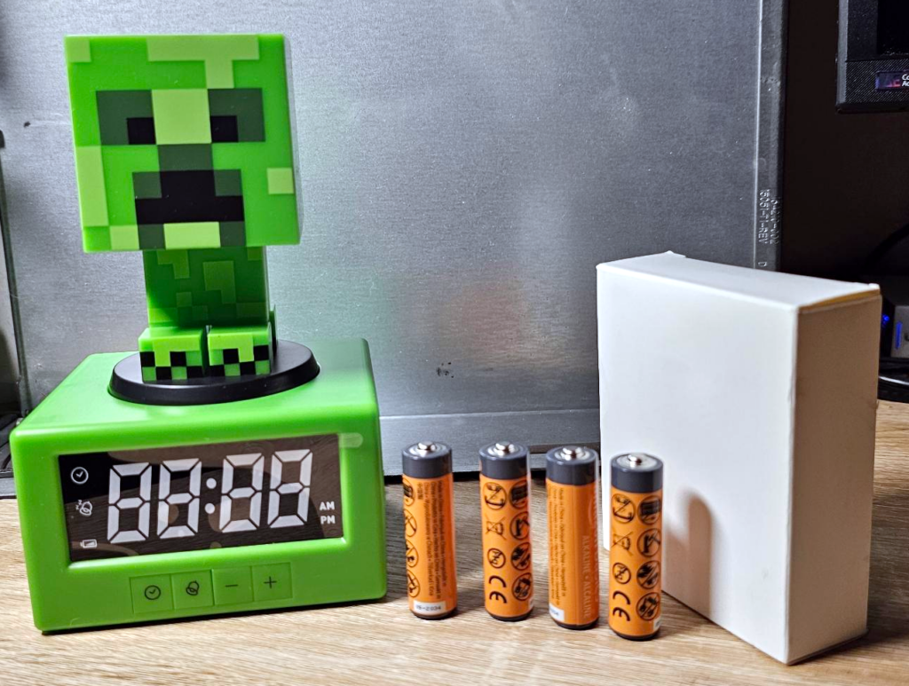
What you’ll need:
- Device that takes batteries and does not have another method to energize (usb, etc)
- A screw driver capable of opening the device
- A soldering iron
- A wall wart (more on this soon)
Optionally:
- A multimeter
- Ideally a panel jack for a barrel plug, or a pigtail (which is what I feature)
- Solder… You may need it, maybe not
Calculating Wall Wart
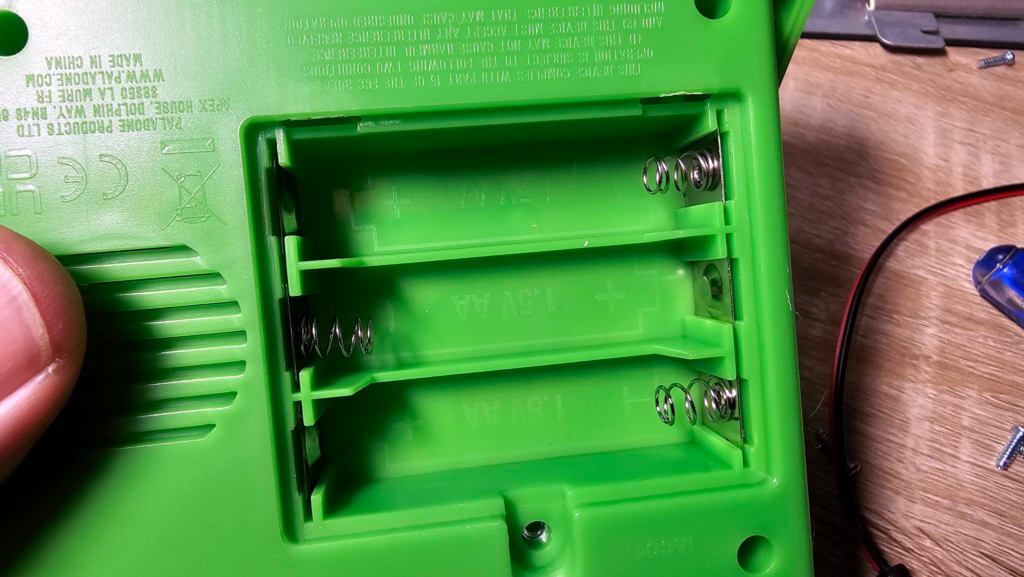
This isn’t exact, but the easiest way to figure out what kind of wall wart goes as follows:
How many batteries does it take? Most batteries are 1.5 Volts at full charge (think AAA, AA, C, and D). Exceptions are 9 Volt batteries, which are somewhere between 9.0 Volts and 9.0 Volts. Gasp. Also, coin cell batteries which are almost always 3v. etc.
Also, we have to consider amps. I’ll generally figure about 0.25A per battery. It really really depends on your use case. An alarm clock powers a small screen and a speaker. A toy car or cassette player (or other motor-based device) might take more. If you want to ensure you’re safe here, I’d say you should review the product details or use a multimeter and make the device draw as much current as you’d expect in its operation (playing a tape, welding 3″ stainless steel plate, etc) and then double it for margin.
In this case, the device takes 3xAA batteries, so it’s safe to assume that we’re looking for a 4.5vDC with at least 0.75A of available power.
But wait, wtf is DC?
The power in your wall can’t make up its mind. It changes it 60 times a second (or 50 times a second if you lack freedom). That’s “AC” or “Alternating Current”. Batteries don’t make AC, they make “DC” or “Direct Current”. That’s why there’s a + and a -…. Your outlet doesn’t have those.
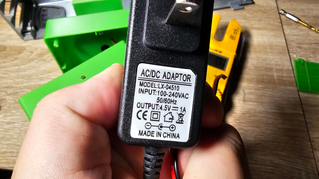
This one is perfect — it’ll accept “100-240VAC @ 50/60Hz”. What this means is you can pretty much plug this in everywhere, as long as you have an adapter.
The output is 4.5v, 1A. So that’s perfect. But see the icon that looks like a long dash above broken lines? No. That isn’t half of a street. That’s the DC logo, that means this adapter is made for outputting DC. Perfect! Don’t tell Marvel we’re part of the DC universe now.
Looking further, you’ll see “CE” and some other logos, which simply means that China photocopied the logos on American-made adapters. The last one however shows a garbage can with an “X” through it. This is important since it means you cannot throw it out. This is how I convince my wife that my hoarding is legitimate.
LASTLY: There’s a minus sign in a circle, connected to the letter “C”. This is showing you that the outside of the barrel plug is grounded (negative, or -). The other side (The center of the barrel plug) is positive (+). This is pretty standard but is important to pay attention to, because hooking this up to your device backwards means you have to return it to Amazon as defective and never tell anybody what happened again.
Drill Baby, Drill
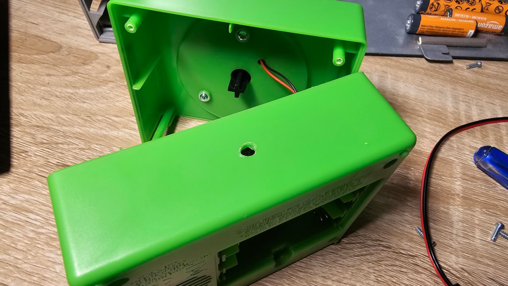
Drill a hole just slightly larger than the wire you intend to run through it.
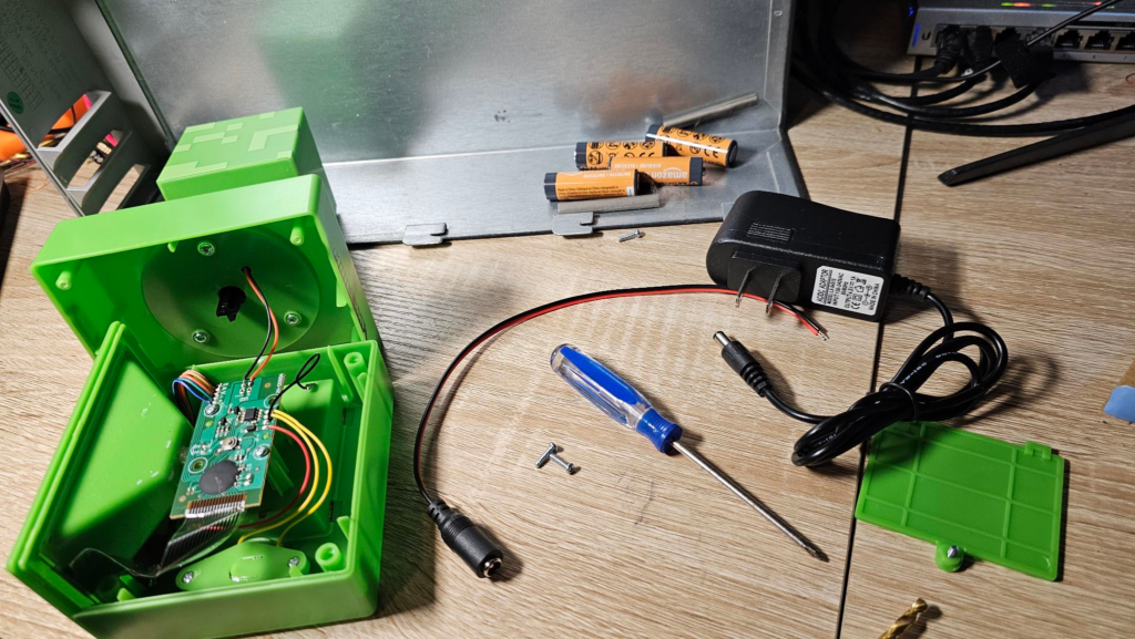
In this case, you’ll see the wall wart with the barrel plug (male) and the pigtail adapter I’m going to use (female) with the black and red wires coming off of it. If you have a multimeter, I strongly suggest you connect your pigtail to the wall wart, plug it in, and ensure the output voltage is similar to the targeted output (sometimes it’ll show a bit higher without load). Also, ensure the polarity is correct — that the red wire is indeed positive. If it isn’t, no biggy, just know you have to hook it up backwards inside your device.
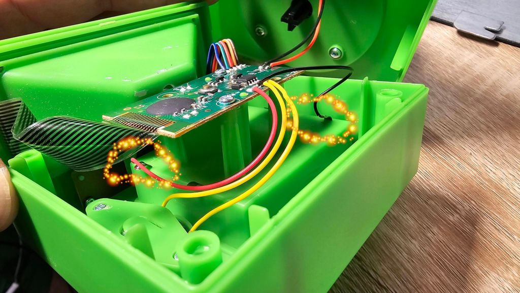
Next, figure out where the power comes in from the battery box. In this case, I’ve added glitter circles to indicate where this happens… And thankfully, the black and red wires line up to negative and positive wires as expected.
You have two options here:
- Disconnect the battery box wires — this disables the use of batteries later (but does make it a little safer as you don’t risk charging batteries until they explode)
- Leave them attached
I did the latter.
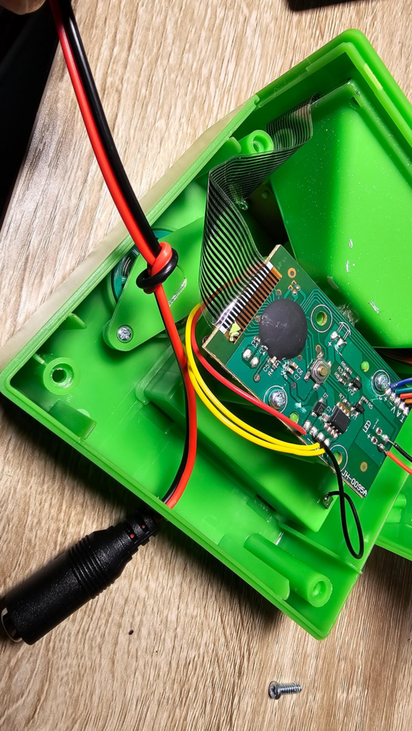
Pull your pigtail through the hole you drilled and tie a knot. This is important as it prevents the wire from getting pulled off of the board inside or doing damage later on. It also helps relieve some of the strain. If you have a panel mount jack, that’s going to look a lot nicer and be even more durable and the knot won’t be mandatory, I just used the shit I had on hand.
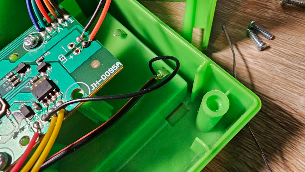
Attach the black wire to the black wire, the red wire to the red wire using a soldering iron.
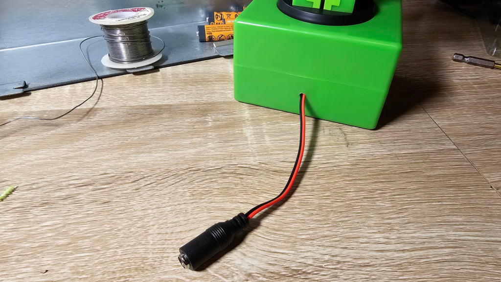
Close it up and plug it in…

If you didn’t let out the magic smoke, you’re done! Congratulations!

Leave a Reply