Hi owners of Ford Broncos! This is for the kids ride-on bronco. Sorry!
Last Christmas, Santa brought my children something I always wanted — a ride on car! (People call these Power Wheels, but it isn’t a Power Wheels). Around the same time, I was into 3D Printing, and had designed an entire hitch system for it, and I also made a license plate for it as well.
Sometime later, my friend and father-in-law flew down to visit and one of my neighbors were getting a new fence. We filled up my truck, and a few weeks later, I went to town building the kids a fort. I also had laying around a 100-Watt Solar Panel kit from Harbor Freight. I bought it a few years back and used to use it for supplementary light for my chicken coop and a tool cage for my tractor.
At first, my plan was to do it lazy, using just the fence panels. I quickly realized that these were just too rotten to use like this, and I’d end up having to butcher the planks.
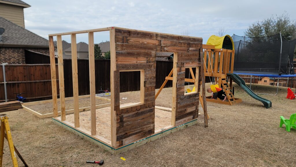
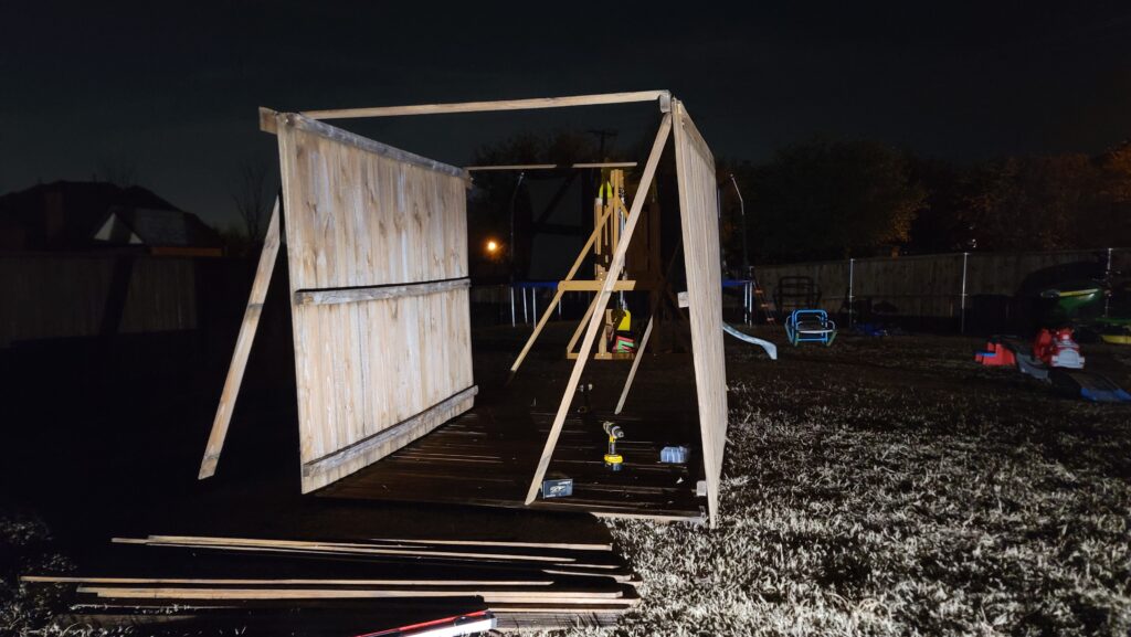
On the ground, I had built out the frame and then cladded it in fence planks. The idea was to build out a fort that had a “Western False Front Architecture” vibe to it.
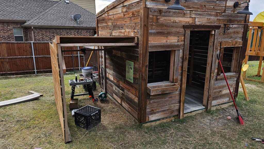
Here’s an idea of what that looks like:

The idea was to make the front look really cool, even if the rest was whatevs. It was built all 24″ on center, and the roof of it holds me, though it was a bit uncomfortable.
Several months later, I decided it was time to add a garage (in the interim, I had also wired it up with that solar panel kit at a few 12vDC lamps).
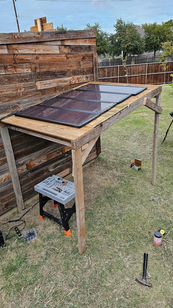
Initially, I sized it so my oldest could sit in it with plenty of room to drive out, and walk around as well. I built out the first cut as a covered carport — and I relocated the solar panels that had been stuck in the mud (and covered in feet of snow back up North). These aren’t aimed for optimal power generation or to keep stuff off of them, but they’re not on the ground and getting smacked by the weed whacker anymore, so that’s helpful.
The way I originally ran the power was via a 5/8″ hole in the back from the panels, to a solar charge controller mounted inside of an ammo can, and then I had a 12vDC motorcycle battery in a big ass marine battery box.
NOTE BEFORE YOU DO THIS: This is how I did it, not how to best do it. There are things I have on order (like fuse blocks and voltage displays) that will improve the safety of this. That said, I’m tacking wires to wood that carry electricity, using low temperature thermoplastics (Polylactic Acid / PLA) to 3D print mounts and components. I believe I did this correct for my risk tolerance and understanding of electricity.
First things first, I wanted to get this mounted a bit better. I was sort of at the end of my desire to work on this last time, but it wasn’t a safe way to do it.
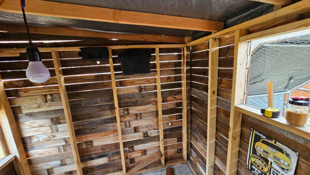
I relocated the battery box and solar controller to the ceiling-line, and of course secured it with heavy construction screws and washers to rule out it falling on the kids.
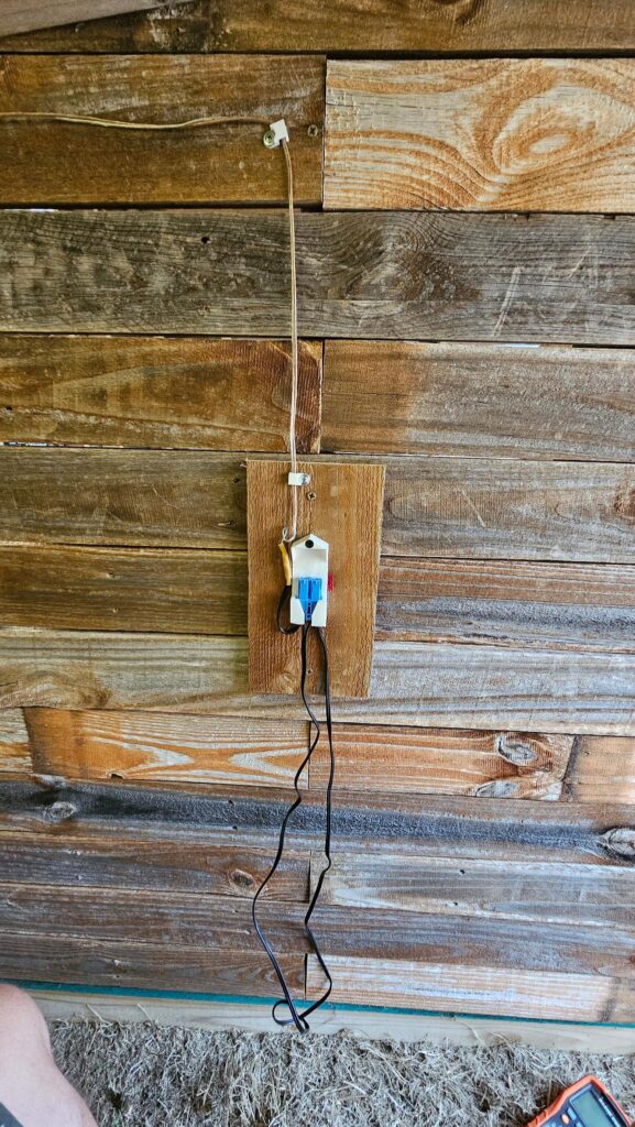
Next, I got the one side of the garage cladded, and I installed a cheater light. I call it that because I originally wrote down that I need to get these items from Home Depot:
- Switch Box
- Switch
- Switch Cover
- Outdoor A19 Bulb Fixture
- 12vDC A19 Bulb
But you know what is actually cheaper and a ton faster?
Buying an all-in-one motion sensing, 10 watt 12vDC light. I can wire it in, no switch, and I also don’t have to think about it being left on and killing the battery. Visible here, you can see just that.
But at that point I realized that my kid’s Power Wheels is a 12v car, that I really want to teach them the finer points about how electricity is generated, stored, and used, and give a tangible reason for them to turn the damn lights off in their room.
It’s funny — when I was a kid, we had these fixtures that had two, 75-watt bulbs in them (150W total). Now I’m having the same conversations with my kids that my father had with me, except these are now LEDs and draw maybe 6 watts in total. Guess terrible energy prices and a failing economy make even 6 watts important!
So, I started planning out my attack. Home Depot and Lowe’s is like a 30 minute drive away due to traffic. Ace is closer, but they wanted $3 for a hose clamp the other day and Amazon wanted $17 for 120 of them. So, to save time and money, I figured I’d use stuff that has been sitting in my garage forever.
Here’s what I found:
- ATO Fuses, the kind that used to be the only kind in cars. I went to a U-Pull-It in Blue Island, IL back around 2003 and grabbed a coffee can full of fuses. I only have a few left, probably left the rest behind somewhere.
- Speaker wire — I had bought some for, well, probably speakers. It’s 18 gauge, which isn’t great.
- Component box, full of heat shrink tubing, solder connectors, and terminals
- 3D Printer
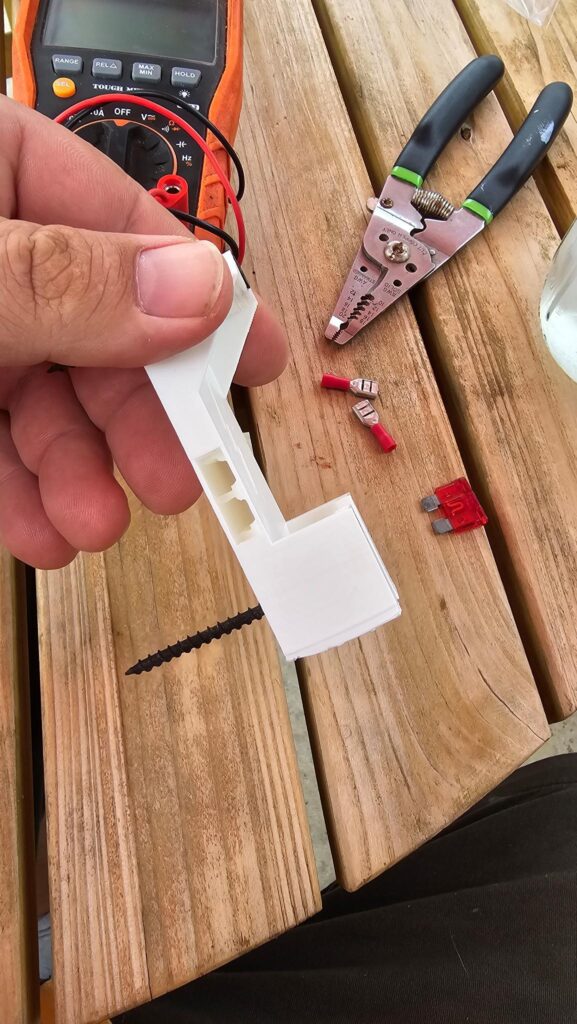
So, I did what any sane person would do… I drew up an ATO fuse holder, which if you want it, you can get it on Printables. It uses a pair of spade terminals and a fuse, it holds it, it protects it. It’s cool.

I then had to make sure that the wire I had on hand was indeed 18 Gauge. I measured the inner conductor (without insulation), and it was 1mm, so it was.
My solar panel setup purports to put out 100 watts at 12 volts. Using Ohm’s Law, we’d take 100/12 = 8.33A. So, our wire has to be able to support at least 8.33 amps without any margin.
LOL MARGIN: Remember: These are substandard Harbor Freight panels that are dirty, cracked, and probably aimed at the moon. We’ll never see 100 Watts. But that’s the rule.
I’m using about 6′ or so of the wire. One page I looked at told me it’ll handle 14A, others are not so reassuring.
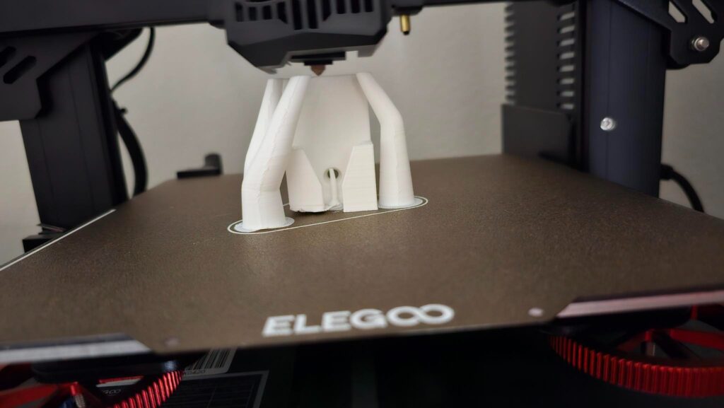
So, my next step was printing a nice holder for the charging adapter for the car. As you can see here, the left side lifted off the print bed for some reason. Of course, if you want this model, I’ve uploaded that tool
The bottom came out pretty ugly, but it’s the bottom.
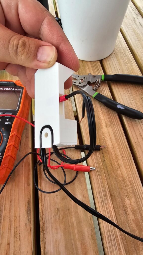
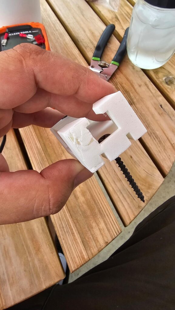
Using the fuse holder STL above, I integrated it into a holder for the charging cable. I ended up finding a place online that had the “GRID” style connector w/ plug for like $15. I cut the cord off and am using it with Solar.
I also built in a strain relief so that — in case the wire is pulled, which it will be, that stress goes directly against a screw.
There’s also a small “roof” on it to discourage water from getting into the connector, though it won’t do a thing for driving rain, or walking rain for that matter.
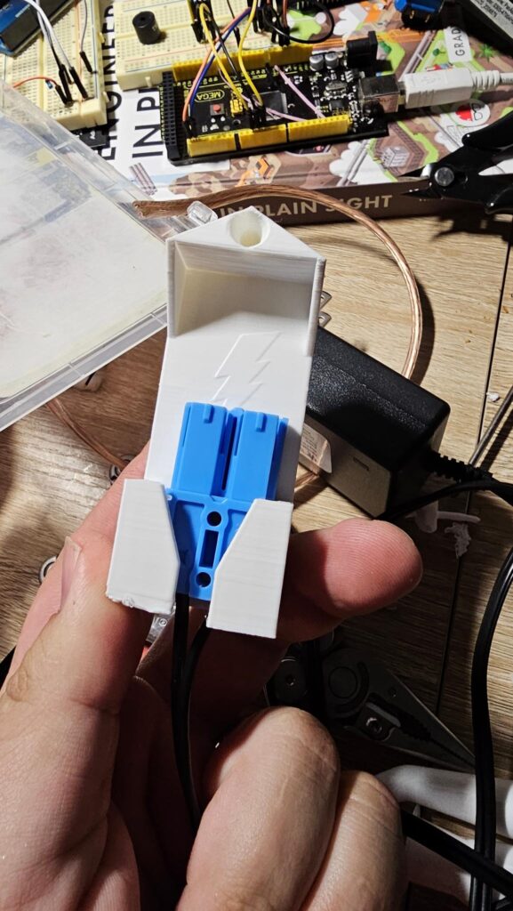
Here it is mounted on the inside of the garage. The butt splice connector on the left isn’t too attractive. I may revisit this design later and hide that, but for now it is fine. You can also see the 10A fuse on the right hand side. There are two spade terminals crammed into the left side.
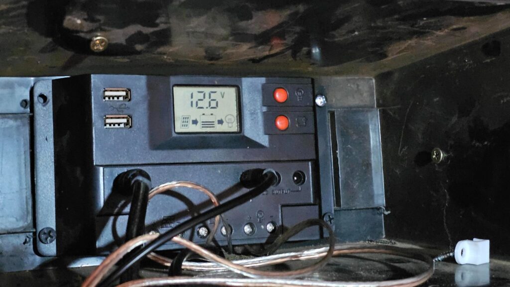
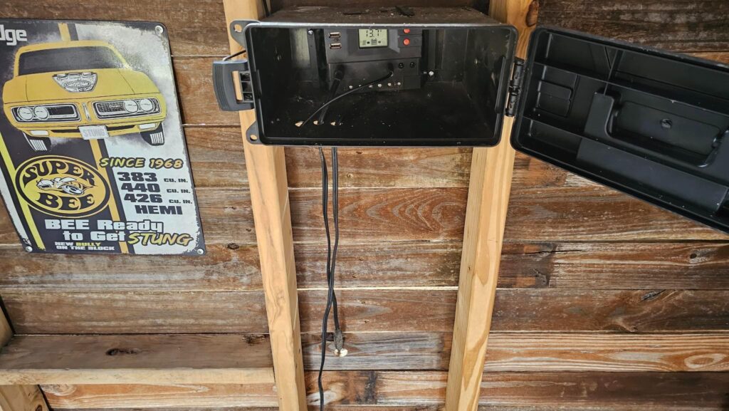
At this point, I re-attached the normal solar battery and the panel feed to the charge controller. I then plugged in the car and hoped for the best.
12.6v when we were getting 13.7v earlier backs up that the car’s battery is attached now. The voltage drop is due to the fact that battery is out of juice. Annoyingly, this and cleaning up the yard took most of the day, so a bit after this picture the sun went down and the car was never charged.
For those wondering: The battery for the car, when attached, is introduced in parallel with the building’s battery. They’re both 12v, so this means we get an amp hour boost without any other real changes.
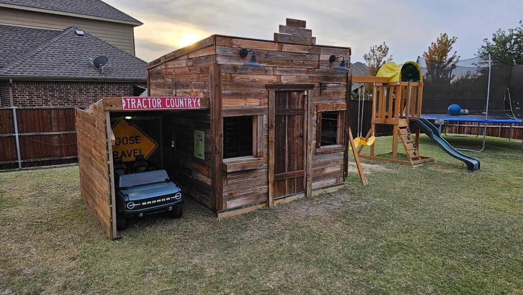
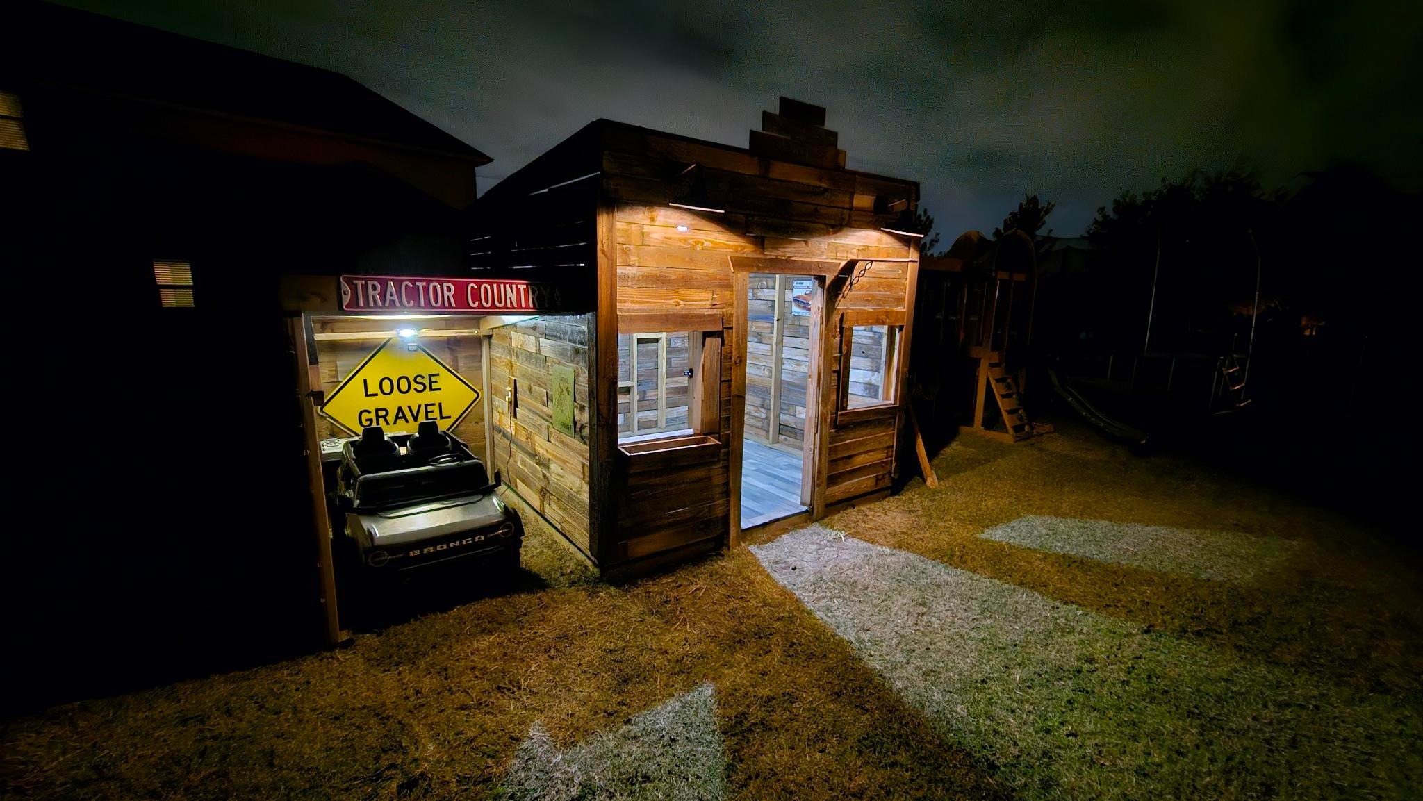
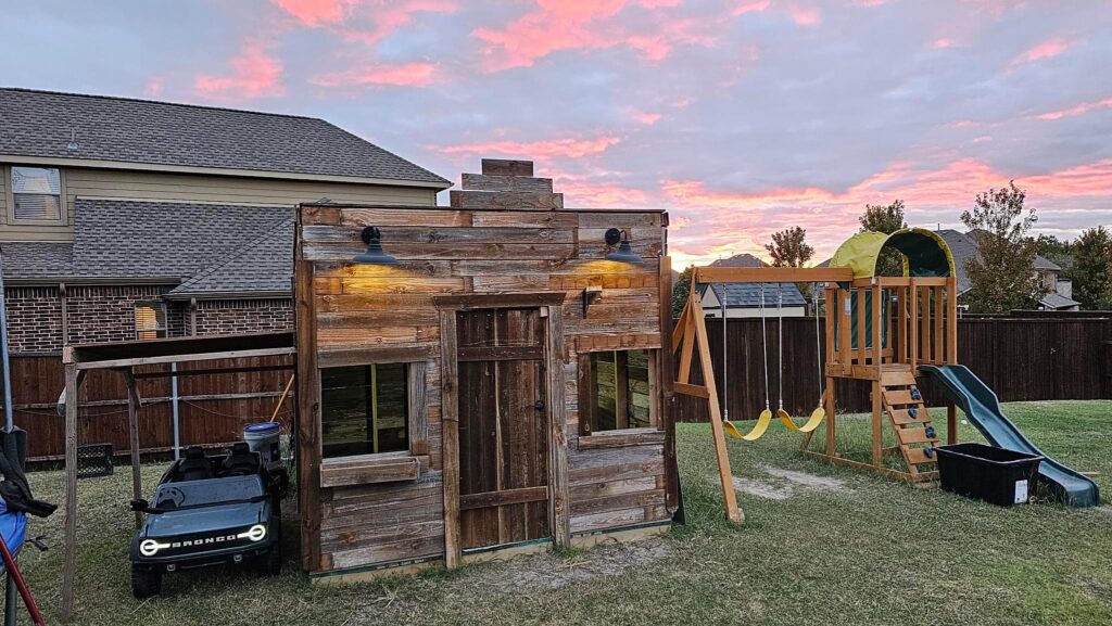
Here’s the completed project before nightfall.

And again later on, with the car on charge.
Drop a comment below if you have any questions on how this was done. Mind you, all comments are delayed, so if you do, check back later for it to be approved and replied to.
Leave a Reply