A few weeks back, a friend was over for some prison wine. We decided we’d karaoke and have a good time, but I was having an issue finding a microphone. I had casually remarked “Well, I’ll just go 3d Print one”, and he said “There’s no way, right?” and I replied “Of course not!”
Challenge Accepted
While I can’t make a 100% 3D printed microphone, I can likely manufacture a good share of the components. Some I can’t manufacture:
- The Magnet: Yes, if you have a metal 3D printer, you could make a cylinder and then magnetize it. I don’t have $80k for something that won’t even make it to Hackaday.
- The Voice Coil: Yes, they sell conductive filament, maybe I’ll do a follow up one day.
Sadly, the above is most of what you need to build a microphone.
I think I’m probably right about the theories I talk about here, but I’m a Robert Lerner, not a Robert Learner.
My ancestors didn’t even learn how to spell “Learner” right.
How Does a Microphone Work?
Fun fact: A speaker is a microphone and a microphone is a speaker. Just like a generator is a motor and a motor is a generator.
The basic premise of a microphone is that there is a coil of insulated wire that is wrapped around a cone, with a magnet in the middle.
Let me illustrate this with my new Computer Aided Drafting tool (CAD):

This is a “cut” view directly down the middle of a speaker. Remember the two are the same thing. It’s true. Google it.
The black part would be the membrane, usually made of paper or some other light material. When you look at a speaker, you see the cone going into the speaker box with the round part in the middle.
The red part would be a magnet that is mounted to the “frame” (not pictured) of the speaker.
The orange part is the coil.
As you speak into a microphone, the paper will oscillate, causing the magnet to induce a current in the voice coil (this will get more visible later when I make the darn thing).
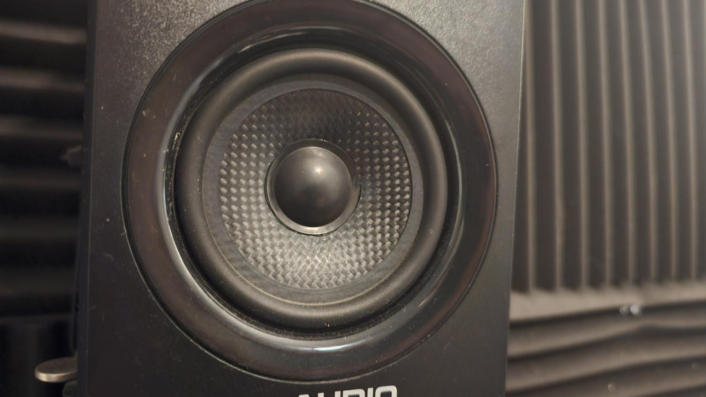
Here’s a front-on view of a speaker. See the circle dome in the middle? That’s the round part in my drawing.
That allows the speaker membrane (the carbon fiber bits) to move freely along the magnet.
Designing the Microphone
3D Printers have some constraints. The fundamental frequency of the membrane dictates its frequency response — that is, if I made the speaker thicc, it could only hear Lizzo.
3D Printers are great at printing thin sheets of things, but not in the air, so I likely will not be able to make the membrane conical, but instead flat. That will alter its ability to capture sound to some degree, but I think for this demonstration it’ll work.
Think of a 3D Printer as a hot glue gun that a computer can use.
Nozzle Width: Most 3D printers have a 0.4mm nozzle, making this approximately the wall thickness I can / should use.
Layer Height: Printers can do variable layer height, meaning the thickness of the plastic it puts down. The thinner you make it, the more brittle it is but the more flexible it will be when it comes time to vibrate to sound.
What to collect
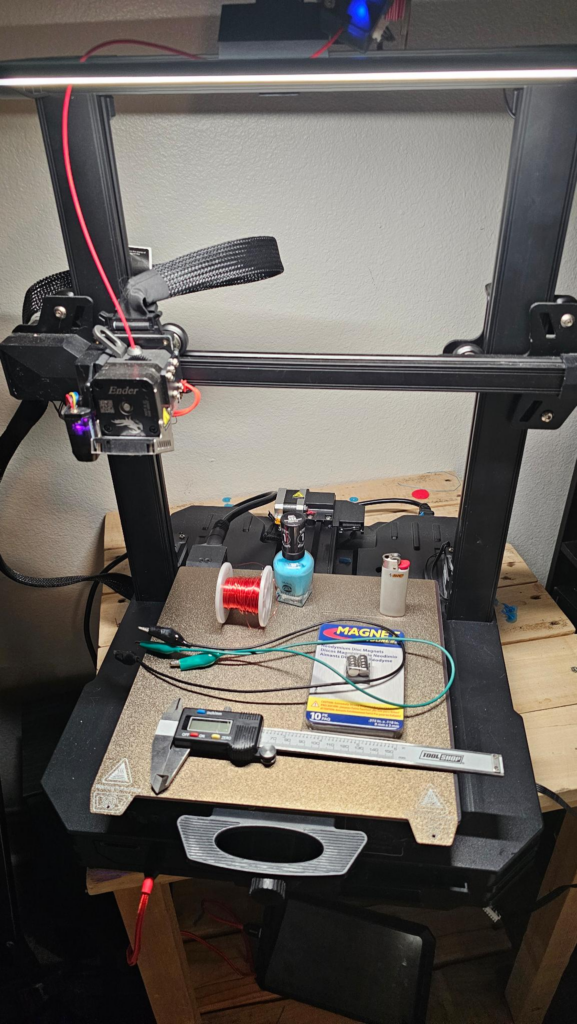
- 3.5mm Headphone “AUX” bawks cable.
- Optionally if you have an Apple phone without a headphone jack, they make these adapters.
- Two alligator clips (Or crocodile clips, let’s be honest, they all look the same)
- Micrometer
- An entire 3D Printer
- 3d Printer Filament
- Varnished bell wire (really thin stuff, thinner the better)
- A lighter (or a small piece of fine sandpaper)
- Nail Polish (or some other adhesive). My wife is particularly fond of this color, while I much prefer the vapors.
- Neodymium Magnets
- Z87 Approved Safety Squint, or glasses
I see you scrolling up to the part where I said the only parts I can’t make are the coil and magnet.
Trust Issues
The package says 8mm, but no. If you chopped a millimeter into 100 pieces, this is exactly FOUR of those oversized. Incredible. Unbelievable. Anyways!
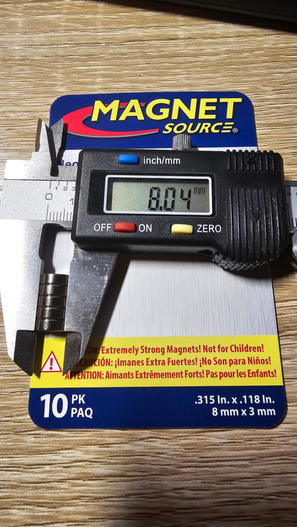
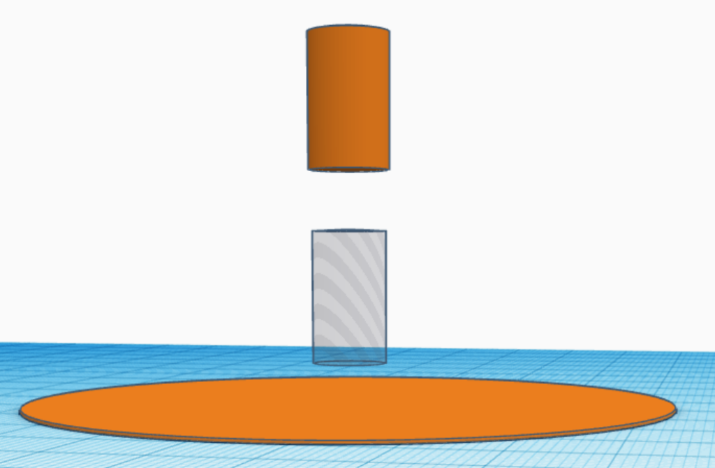
Using TinkerCAD, a professional’s tool, btw, I begin drafting up a 75mm circle (3″ish) and 0.28mm tall (layer height!), I then make a 8.25x15mm hole, this is a touch oversized more than the magnets. I’m not sure if that’ll fit or not but it should in theory. The 15mm comes from the height of 5x3mm magnets, which I measured to be 14.98mm. Close!
Why 75mm? Not a good reason. The problem is, the bigger the membrane, the more sound it can collect. Conversely, the more weight that needs to vibrate to produce sound. I’m sure there’s a sweet spot here between frequency response, weight, cost and size — I’m just not going for optimal, just possible.
I’ll add a 9.05mm cylinder, also 15mm. This will be where the coil mounts to. It accounts for the 0.4mm nozzle width, but it may make the coil carrier (the tube) a bit tight.
Finally, I’ll add a few tabs that will work as the suspension of the speaker (mounts it in place, but doesn’t hold it perfectly still):
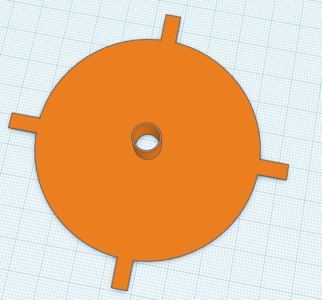
A few people have asked “Is 3D Printing Expensive?” and “How much is that part for your blog?”
Joking, nobody asks me anything.


This specific part will take 14 minutes to manufacture and cost a whopping 3 cents. I’m sure it is rounding up if I’m honest.
Microplastics

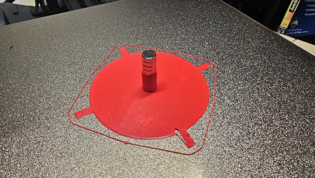
The magnets will go in and they’re really snug AF! Terrible if you want it to move freely! Also, there’s a defect in the part closest to the camera. So this one will become microplastics!
Updates!
- Made the coil carrier conical and expanded it. Attempting to reduce chances for it to hang up on the magnet edges
- Added some tabs to the suspension for alignment
- Added a small notch to channel the coil out to the frame
- Changed the thickness to 0.2mm for the layer height, but then printed at 0.28 anyways. Whoops.
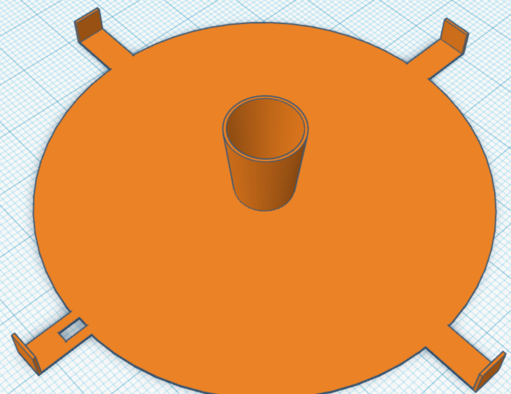
Now that I’m hitting print, I suspect the conical part in the middle will make the coil winding a real pain in my ass. That’s a problem for future Bob.
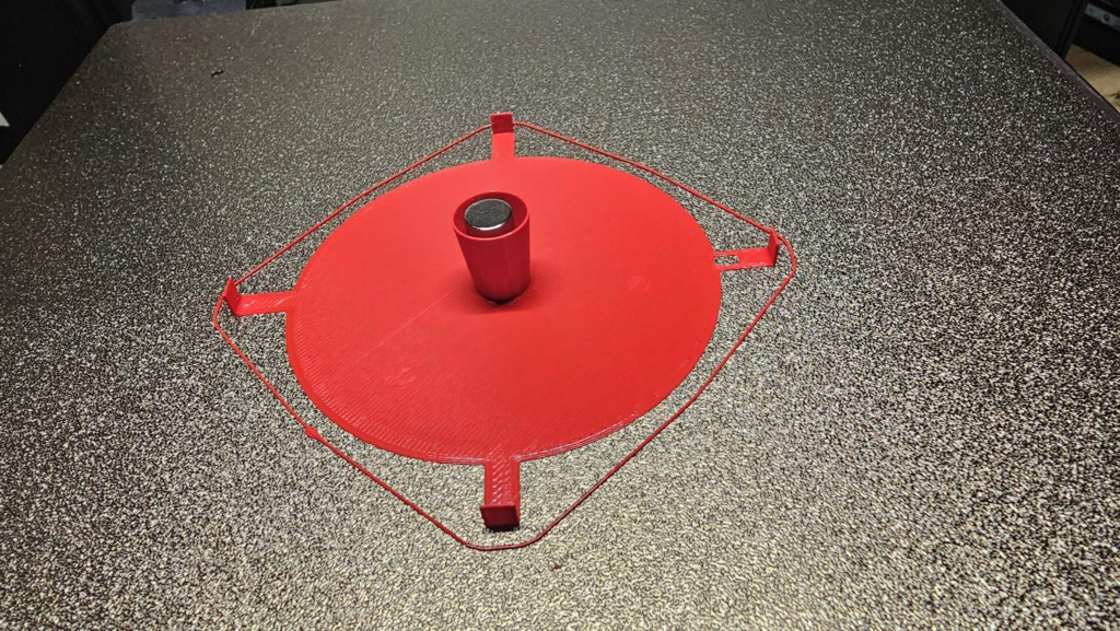
Making the Frame
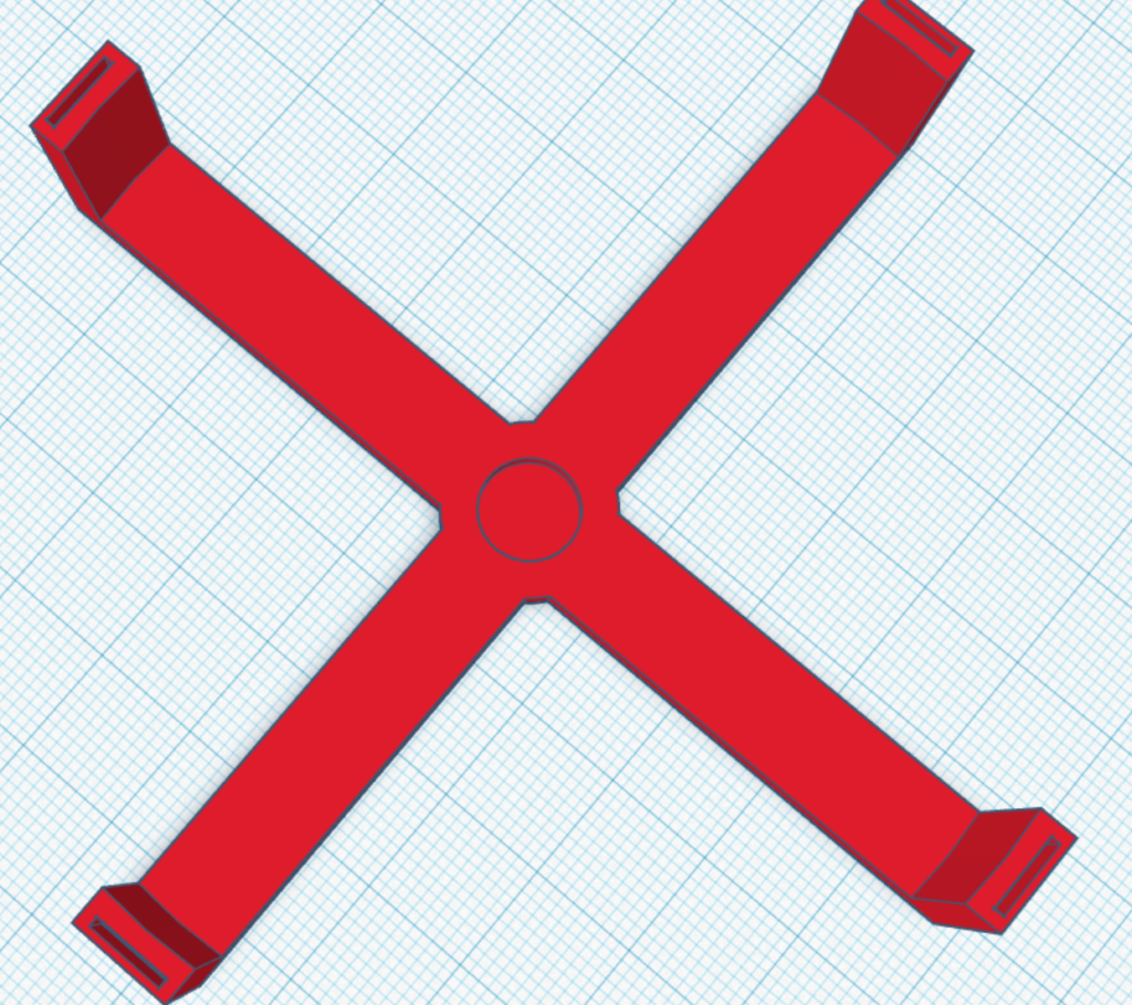
It doesn’t have to be light, but the lighter it is the less material it uses and the faster it’ll print, so this should be just fine. You can see the recess in the middle for the magnet to be glued down, and the four mount points for the membrane. Going to print this on the other printer for color contrast. I get the vibe (get it, vibe?) that this will take a few tries, though it shouldn’t.
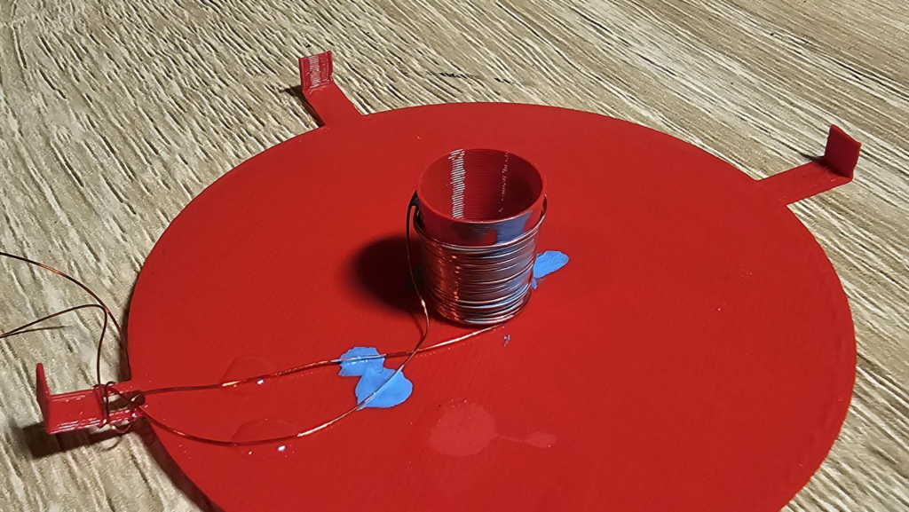
I know, it looks like hell.
The nail polish didn’t bind as well as I had hoped. Also, using red wire and red filament makes it less easy to see. The conical part didn’t making winding all that hard, but those tabs on the edges sure did suck.
I decided to do only one layer of wire. This is an effort problem, not a practical problem. If it doesn’t work, I can add a few layers of windings and probably ditch the conical shape.
FUN FACT! Before becoming a welder at a factory, I actually would get paid to watch cable go onto a takeup reel. This isn’t me or my old work, but it is similar:
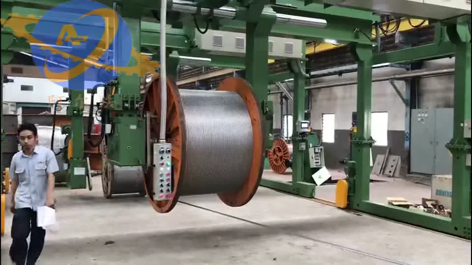
I’d have lost my $7/hr job if my winding looked like tonight’s speaker!
Getting Wired!
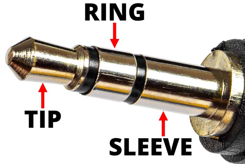
The frame is taking forever to print, so lets talk about audio cables. You’ll see three components to most of them:
- Just The Tip: It’s the bulbous part on the end of the wire, this is a (+) positive signal-ish, and corresponds to the LEFT side of your audio
- The Ring: This is the same as the tip, but the RIGHT side
- The Sleeve: This is the (-) ground
This is why one of these cables are used for a pair of stereo headphones, left & right. You won’t need to remember this later at all, because while there is a polarity to the microphone we’re making, I frankly don’t really care. It depends on the polarity of the magnets in the middle. It can impact phase of sound and sound quality, but again, proof of concept.
You MAY have one of these where the sleeve goes all the way up… That’s a mono cable, it will talk to both channels but the two are effectively shorted together. That’s fine, because we only have one microphone so only one signal to send.
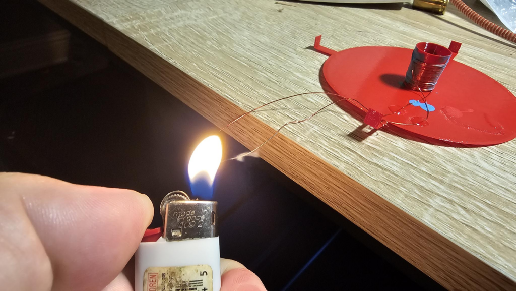
Next up, use your lighter (or sandpaper if you don’t want cancer) to remove the last few mm of varnish from the wire. This smells great!
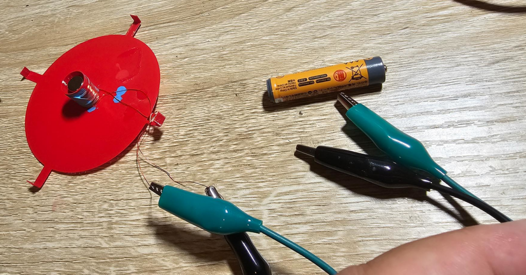
You can now place your magnet stack in the middle and hook the ends up with alligator clips. Briefly tap the other end to a battery and you’ll see the magnets jump out or the membrane jump off. If so, you have a valid connection! Don’t hold it on too long as this wire will burn up and your work will be a total waste.
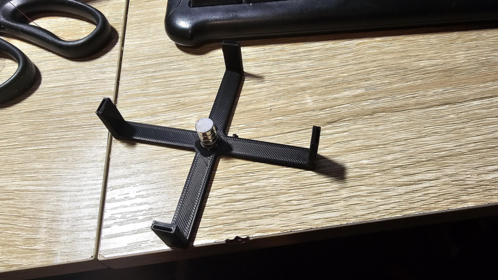
Next, grab your frame and glue the magnets to the middle portion.
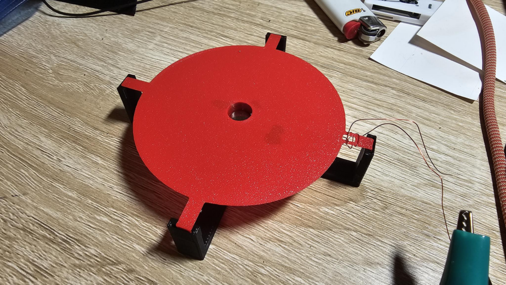
Slide the membrane over the magnets and into the tabs. In this case, the tolerances are tight enough that the layer lines are actually hanging onto the membrane quite well.
Does it work?
Yes actually, as both a speaker and a microphone. But surprisingly poorly, like worse than I would think.
As a microphone
I attached it to a few computers that I have to see if I could get any sort of reading in Audacity, however modern sound cards or something else won’t see that a microphone was attached — likely due to the fact that I made to effort to ensure impedance / resistance / etc were in spec for something similar. Might revisit this.
That said, I plugged it into an amp and tapped on it and it came through sounding like you’d expect, a bit of a drum pad effect. Kids are in bed, so I can’t scream at it and see what comes through, and frankly, I’d want to record it and see the response.
Originally I planned on making a frequency sweep that also monitors the input levels to try and get a speaker + this mic vs. a speaker + real mic frequency response graph. I can’t get the data right now with this current design, and I suspect I need to make the membrane even thinner and add more turns to the coil.
As a speaker
I hooked it to my Xubuntu laptop, which allows you to overdrive sound. I turned it up to literally 11, and then made sure the audio file was full volume. I couldn’t hear it over the sound of my 3d printer fans, switch fans, computer fans, etc. Turned as much off as possible and I COULD hear it with my ear directly above it.
My phone could not pick up any audio until I got the phone mic right above it as well.
So, in short, it sucks at everything. But that’s okay, because this counts as both a speaker and a mic.
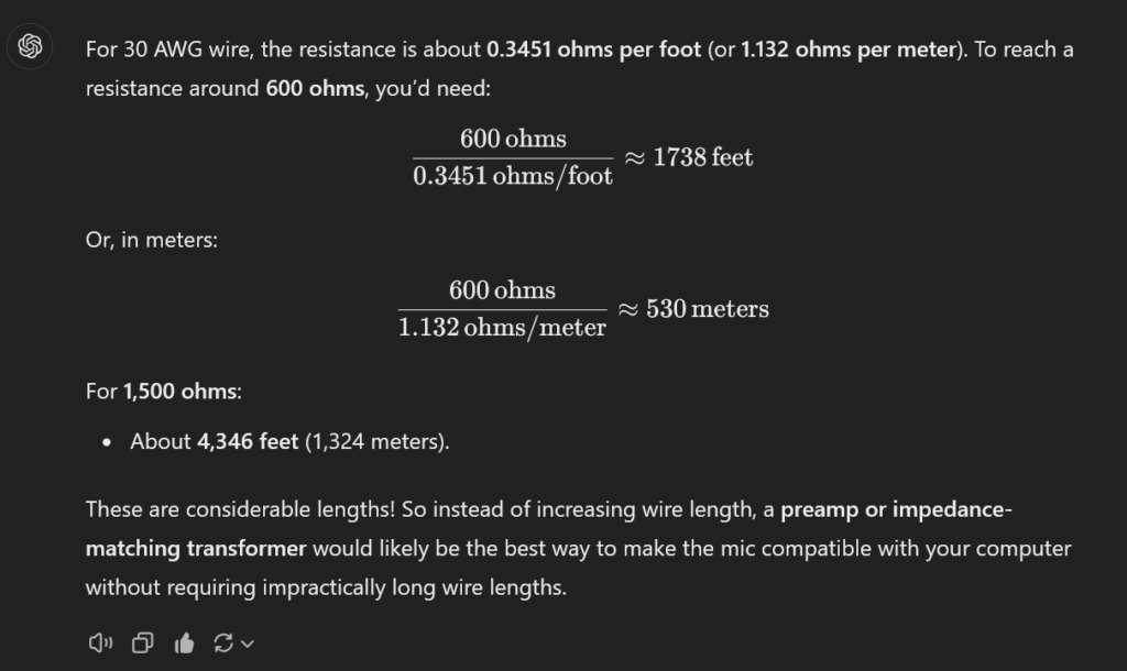
I’m not coiling that by hand.
What’s Next?
If I can figure out a hacky way to get it so I can get you a response curve or upload some audio from it, I’ll do so. I may revisit this in the future and make the proposed adjustments. Still, it was fun.
How is this about security? That smart speaker you own? It’s also a smart microphone.

Leave a Reply