My mother in law was in town and took my wife shopping for her birthday at an antique mall here in town. They stumbled upon a Carolton Cards Phantom of the Opera ornament from 1999 that my wife loved. Other ones were selling for $300 (note there are a few different years and styles, and this one is worth the most I guess). She found it for $100, but also 50% off, and really wanted it, so she picked it up.
Once we got it home, we threw three fresh AAA batteries in it and hit the play button. Instantly, it sounded like Alvin and the Chipmunks and the light was yellow. My wife knew something was wrong and looked up a video showing how it should work. This is what she found. If you really want to hear how this thing should sound, here’s a link to the original song — sample starts at 3:22.
This will likely be a lengthy blog, full of electrical engineering errors and attempts at improvement, it may even fail (I’m starting this before I fix it because it has taken long enough already). I want to send a shout out to Ryan Villarreal, Jaime Cabeza, and Deral Heiland for letting me bounce ideas off of them and making some great suggestions!
Let’s get an idea what is wrong
We know the music is playing too fast, but it also has an unusual warbling quality to it. I initially suspected this was some odd tape loop in the inside due to the age of the unit. The LED being the wrong color, however, sort of suggested an over-voltage of sorts which could potentially cause the capstan motor of a tapedeck to move too fast too. Perhaps there’s a bad component regulating that internally?
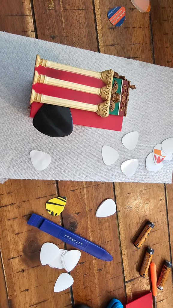
I told my wife (Stephanie) that there isn’t really a great way to open this and “peek” and that it may experience some damage. She said she was okay with it, so I busted out some guitar picks to open it up since the unit had no external screws.
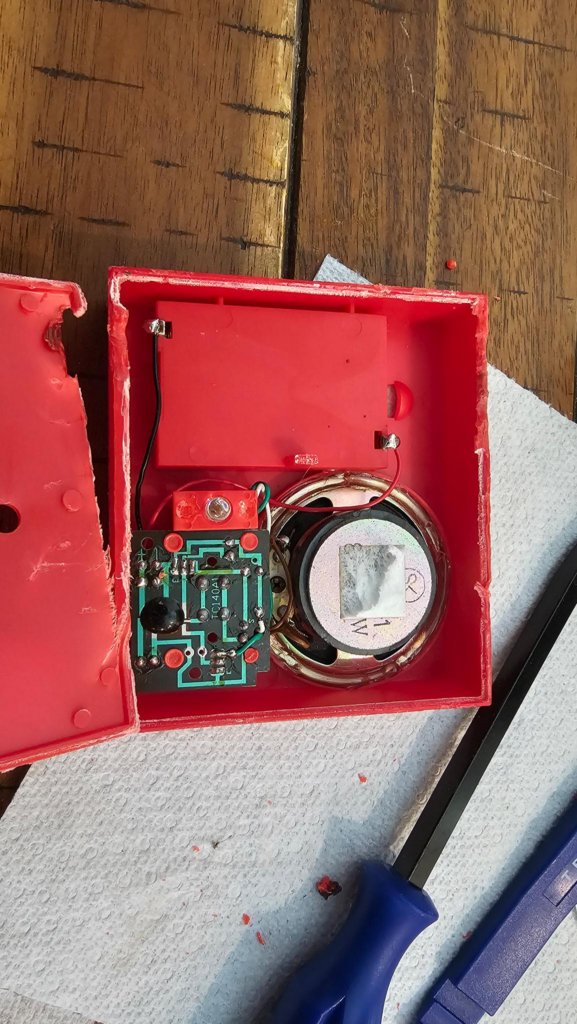
This thing was glued quite well around the perimeter and there were some really uncomfortable cracking sounds happening while I pried on it. That said, I was able to get the back off and this is what was left:
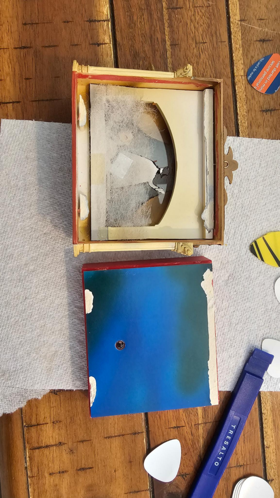
Unfortunately there was a little damage to the “sky” backdrop, but I didn’t really plan to fix it since it would likely be outside of the view of the window. But a new problem happened: I still can’t get to the electronics because they pulled an a-hole move and glued this shut from that side too. Of course, I didn’t know this yet and had to look for screws… So here we go:
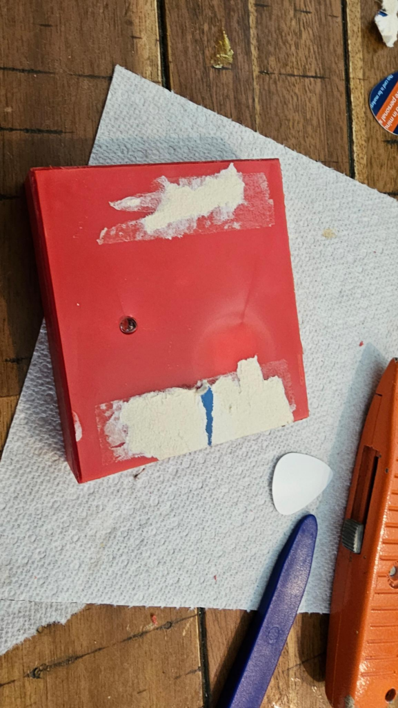
No screws and a completely destroyed background. Damn. It’s a good thing, however, that I took a high-res pic of if ahead of time. I loaded that in GIMP and used the Perspective tool to make sure I had the right angle on it.

I went through, using the Clone brush, and fixed several of the damaged spots in the image (white dots throughout), I also corrected the area around the LED bulb and fixed the rip damage.

I also added a large blue border to it — this will be printed at Walgreens on 4×6 stock, and I wanted to ensure I had the right sized print. This also adds a minor bleed area to the perimeter, and marks where I will need to put the hole for the LED.
I simply used an old gasket hole punch I had laying around (since my normal hole punch wouldn’t reach) and then carefully cut out the background, and now I have a replacement!
Next, I need to open this box:
It’s quite possible a Dremel wasn’t the most delicate way to address this, but I did it anyway. This will be buried inside of the ornament — should I get it back together.
To my misfortune, I see a terrible epoxy blob covering the meat ‘n taters of the circuit. So, I stepped away to design the new cover:
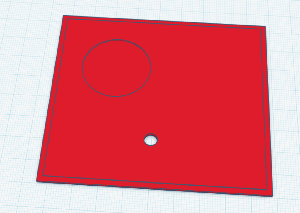
The flip side gave me some relief:

Seeing a capacitor made me certain that this would be the problem. Any old electronic device generally fails due to electrolytic caps leaking and failing. I ordered and replaced both the 47uF and 22uF, but it didn’t improve.
I then went on to check the resistors in the circuit to get an idea of if they seemed right. I can read a 4-band resistor all day long (Because they almost always end in silver or gold) so it’s easy to know the order. In this case, there were a few 5 band resistors with really tight (1%) tolerances, and I had issues reading the values due to color fade and my brain fade.
I hit this with QD Contact Cleaner, and tried again hoping for some weird corrosion issue. That didn’t fix it, but I noticed if I hold the power button down, the color turns green and the music slows down close to where it should be. Figuring the switch may be bad, I just shorted the switch on the bottom with a screw driver, but the same behavior continued.
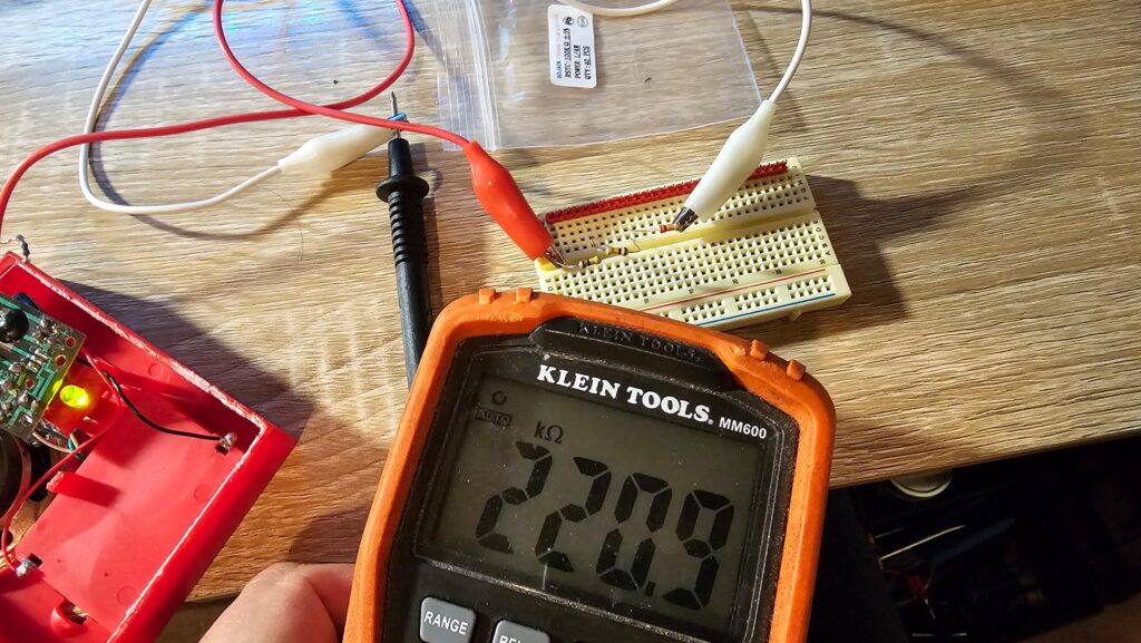
Being low on options, since I really don’t expect a resistor or transistor had failed, I licked my finger and tapped the back of the resistor. The music speed increased the harder I pushed, and that gave me an idea! I was unable to check a resistor in-circuit (potentially), so I pulled it off and threw a meter on it. Being a dumbass, I seen OL (Open Line) and just assumed it was bad, not realizing the auto ranging feature wasn’t set to “auto”. I then incorrectly read the bands and put the wrong value resistor in here (still in the picture below), and no audio came out.
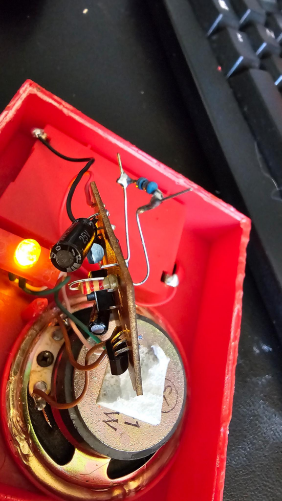
I then made the most gore filled decision to replace the original resistor using the other resistor’s legs to ensure I didn’t smoke anything. It went back to the normal (Broken) state.
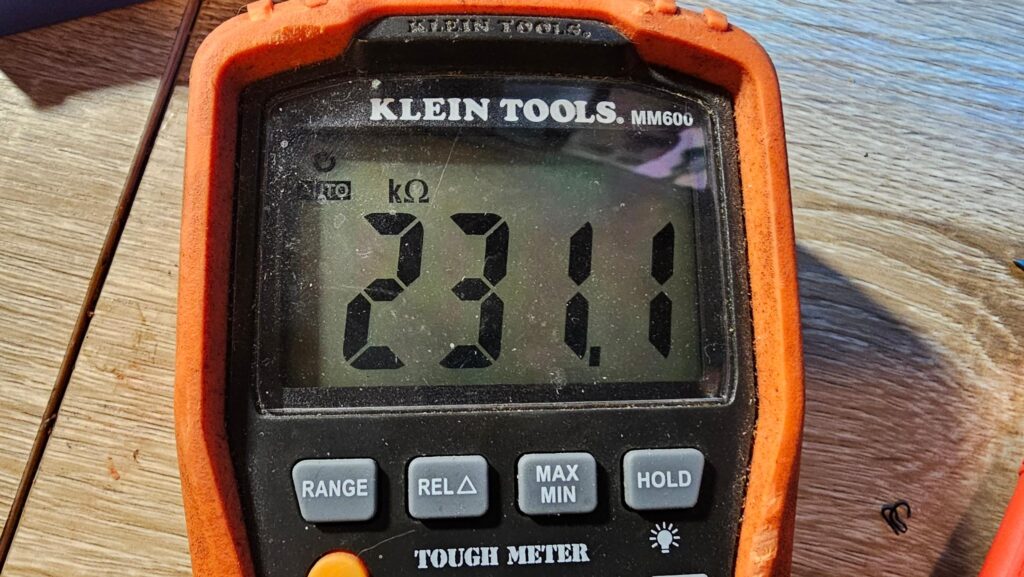
Okay, so 231 KILO Ohms…. That is for sure outside of the initial range of the meter.
This is great because 230K lines up quite close to the band colors:
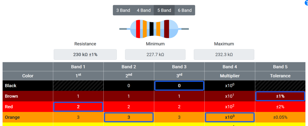
Knowing that this has SOME impact on the speed of the unit, I decided to, once again, cut the resistor off of the board.
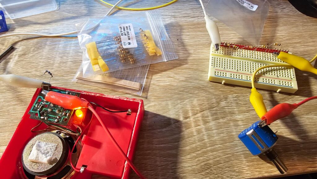
I threw 2x 100K and a 22K resistor in series in a breadboard (222K total, +/- 5%)
I also added a 10K, 10-turn linear potentiometer in series. The thought was that this will take me from 222K to 232K, which may allow me to vary the speed and see what resistance is on-track and then order/make something for it. But, it didn’t make a difference.
I kept brute forcing it, eventually got to 422K +/- 10K and the speed was closer:
But, it started acting weird. I even tried hooking it to my power supply and undervolting it to see if maybe it expected lower voltage NiCAD or something.
With the various resistor swaps and the physical stress on the board, I tore out the contact pad. Yes, I can connect to the trace next to it and keep going, but my wife just wants a working ornament and I can give that to her. I can’t really resell this as a nice original unit anymore after using a burr grinder to open stuff up internally (even though the finished product should be nearly indistinguishable.
18 Days Pass
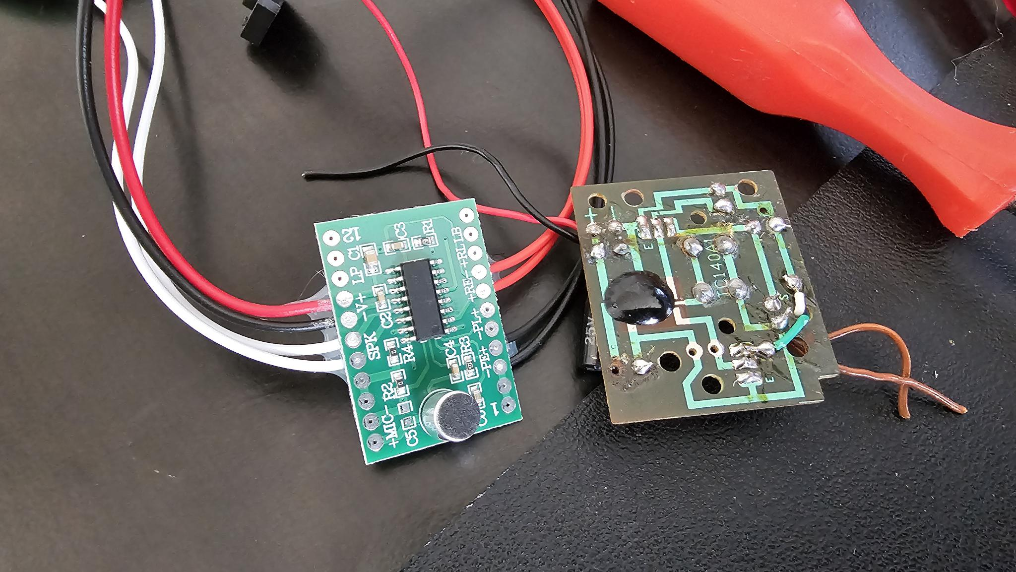
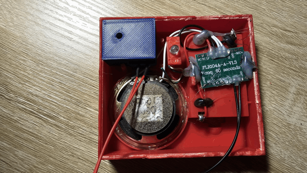
Thanks to China, I now own a voice recorder module:
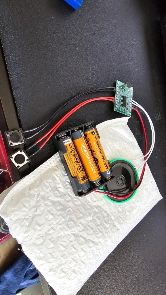
This can record up to 60 seconds of audio and plays it back, runs on 4.5v, but the crap speaker it comes with uses 16 ohm speaker and mine is 8. I think this just means it’ll be louder, but I’m going to do a bit more reading and see if I should throw something inline with it.
Here’s the technology difference between the 2025 module and the 90’s epoxy blob stuff:

You can also see where I tore out the pad in the bottom left.
I cut off or desoldered the components I won’t need anymore:
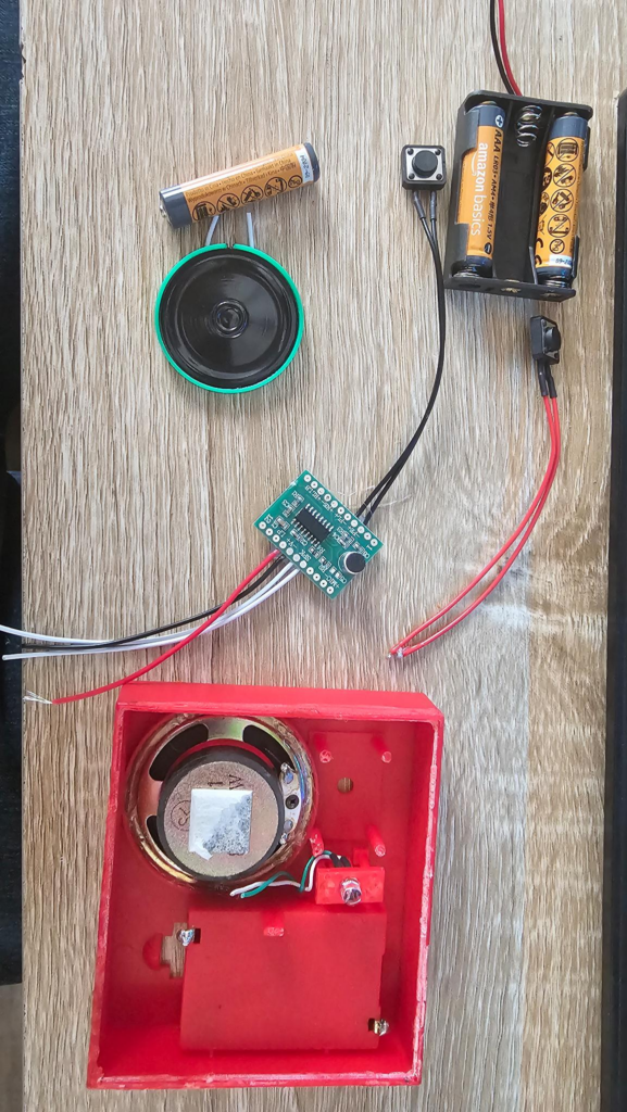
I want to tie into the original speaker, so I’m doing that. I won’t need the record button (and I also desoldered the microphone as that also won’t be needed and won’t fit in the case where I want it to). Finally, I cut off the battery box as I want to use the original.
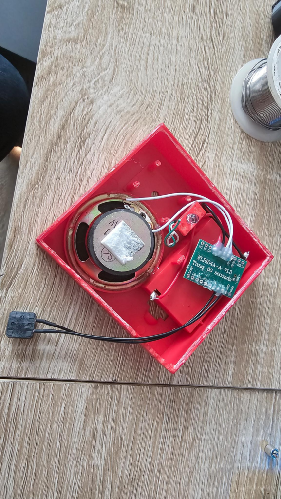
Okay so that’s easy, and it works fine:
But the problem we’re going to have now is that the green LED won’t do anything. Further, that button needs to work like the original, so I need to print an adapter for that.
This is a great project?
Why you ask? Well, the last time I wrote in this blog was March 25th, and still haven’t published it. March 5th is when I started on it. I printed the adapter I mentioned above and wasn’t thrilled with the fit, and threw it on a shelf.
Here we are in April 29th and I’m going to post this blog, because it has been a while since I have. Also — I love this project because the due date is literally Thanksgiving when we hang decorations up.
That said, I’m actively printing a slightly modified adapter, but here’s where the original went wrong:
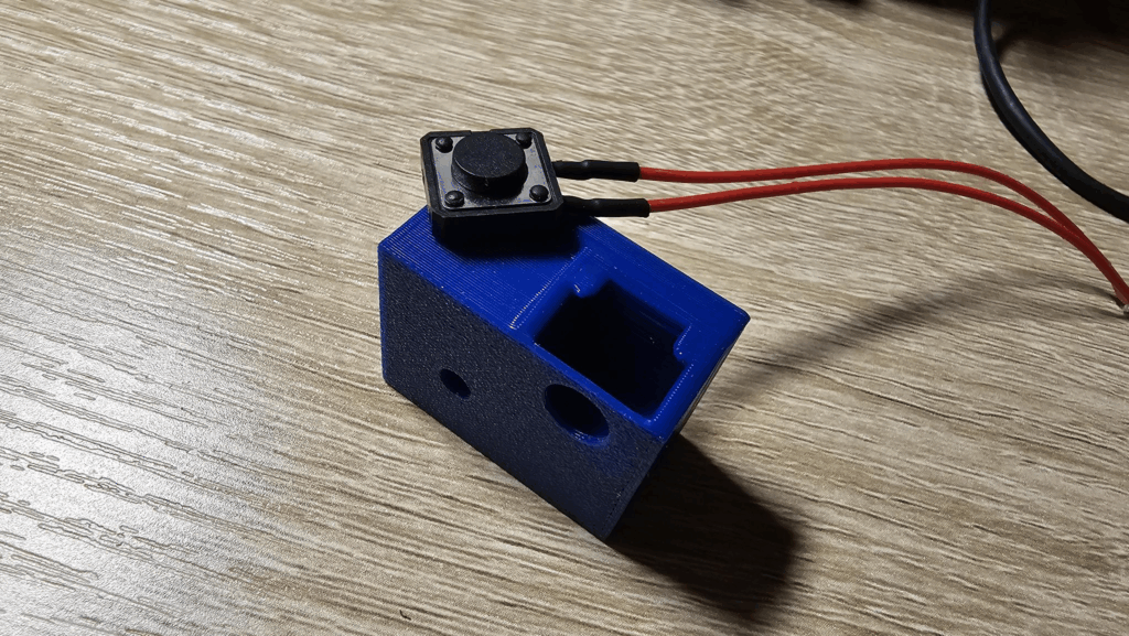
Looking back at it, I almost reinvented the port for my network cable (I’m sure there’s a term for it and somebody is going to come back with DB25 RS232 Core7 64bit Dog5E Adapter).
That slot is to provide a holder for the switch above it, while the hole should hold the original red button and “hide” the fact that it is pressing an entirely different mechanism.
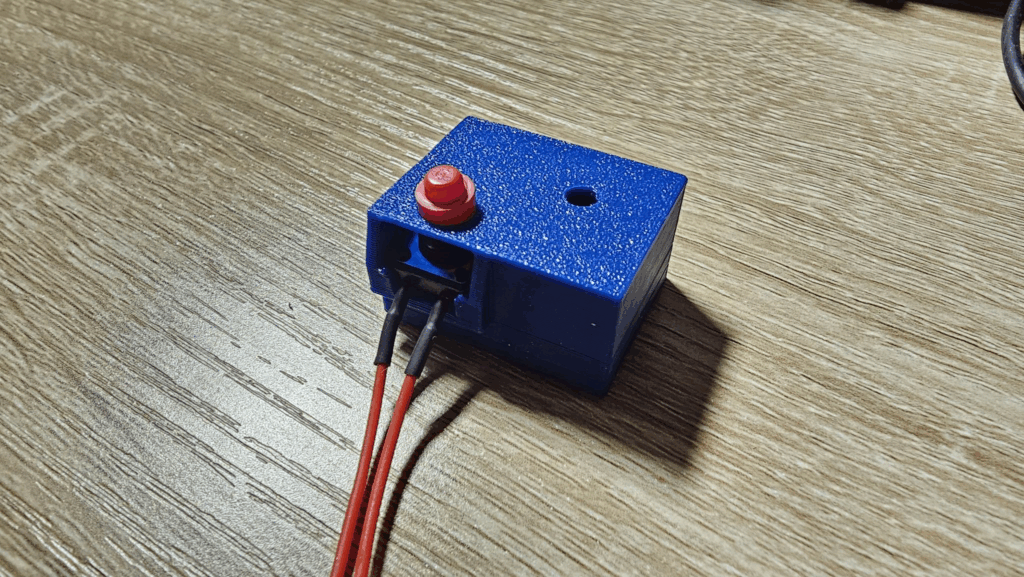
If that’s not clear, here’s it assembled. But, the problem is that I made the button holder a bit too tight, so the plastic part can’t freely travel and depress the button itself without hanging up. Also, the switch is quite tight in there and I’m not a fan. So I’m printing again right now and made a few other small changes, but I think that may actually make it worse. Rapid prototyping, yay!
Here’s the guts, it’s not pretty but it doesn’t have to be:
The plan is to use a resistor to drop down the voltage and a diode to chop part of the waveform out and then funnel that to the OG LED and hopefully get it to flicker, then close it up. Will update later with more!
Want to see how this ended up? Check out Part 2!
Leave a Reply